
Where we stand...
The last post came from a different home/workshop. Since then i've been a bit transient.
The bike is in storage in San Antonio though, and i'm able to work on it from time to time.
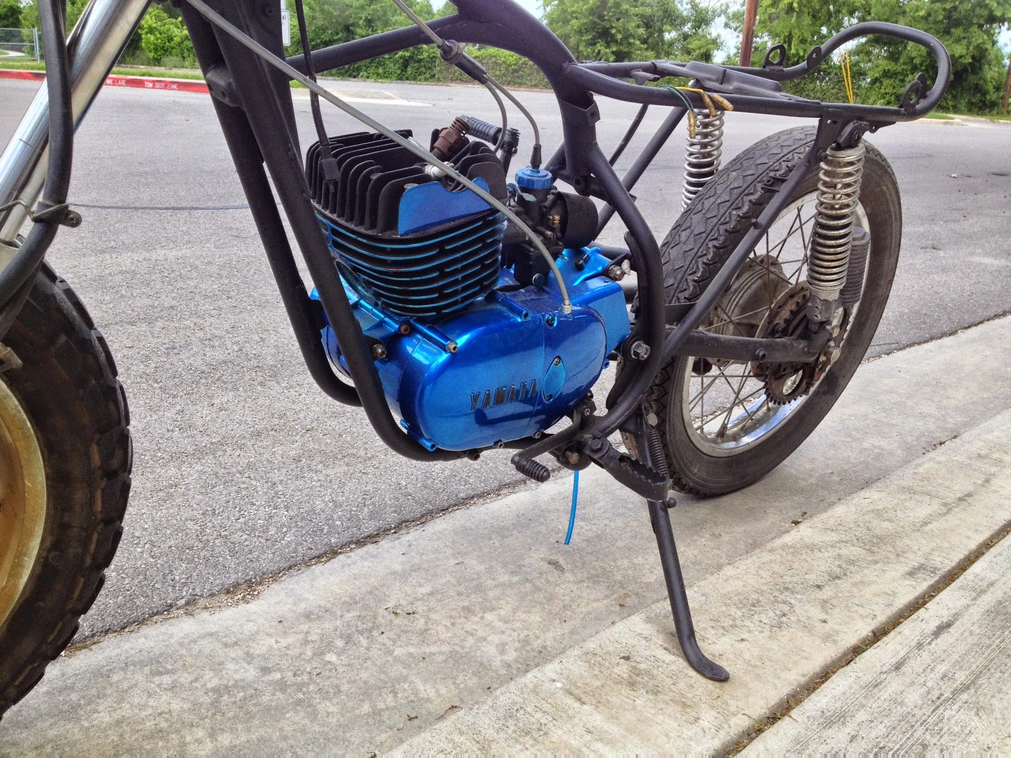
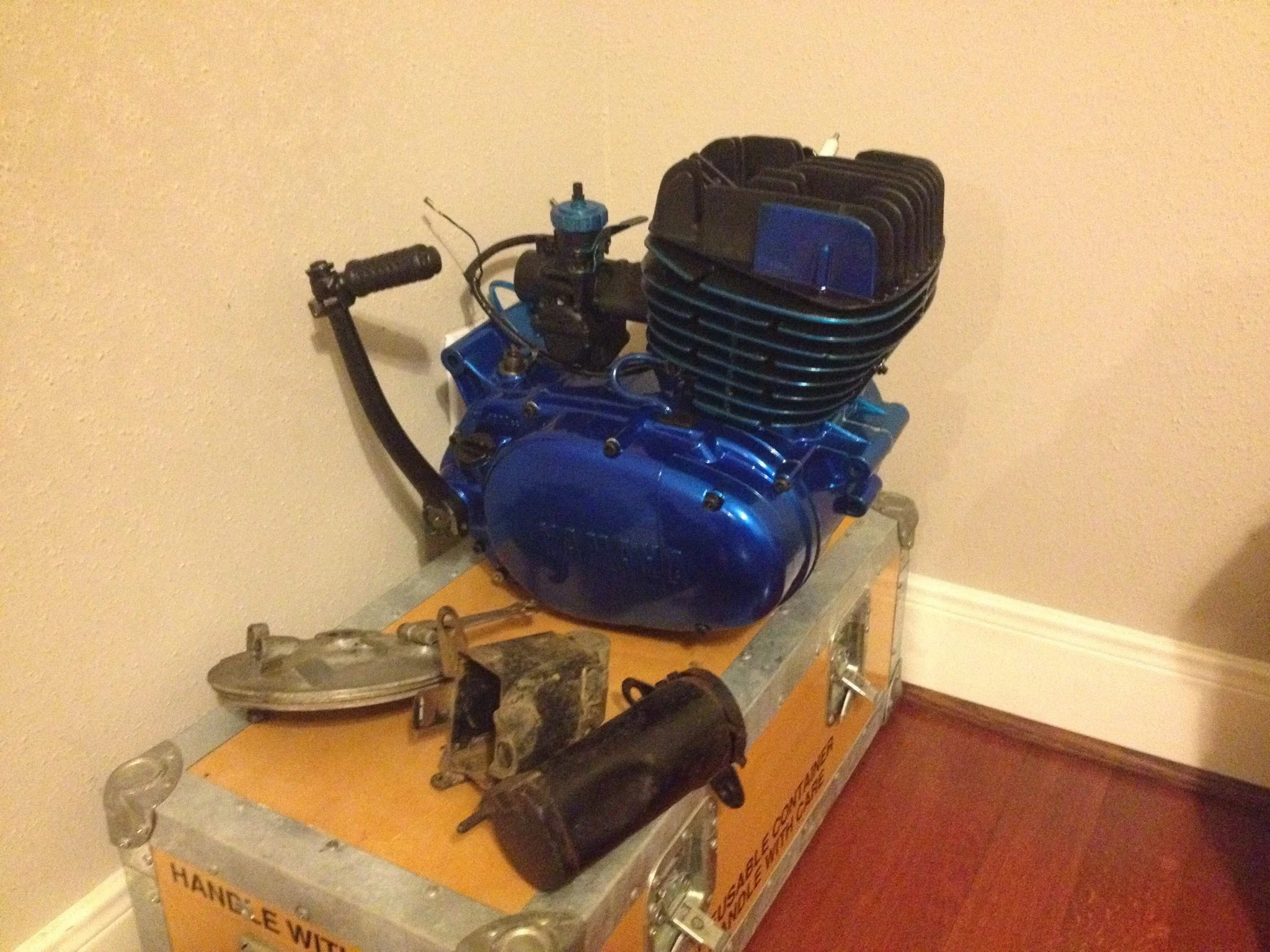
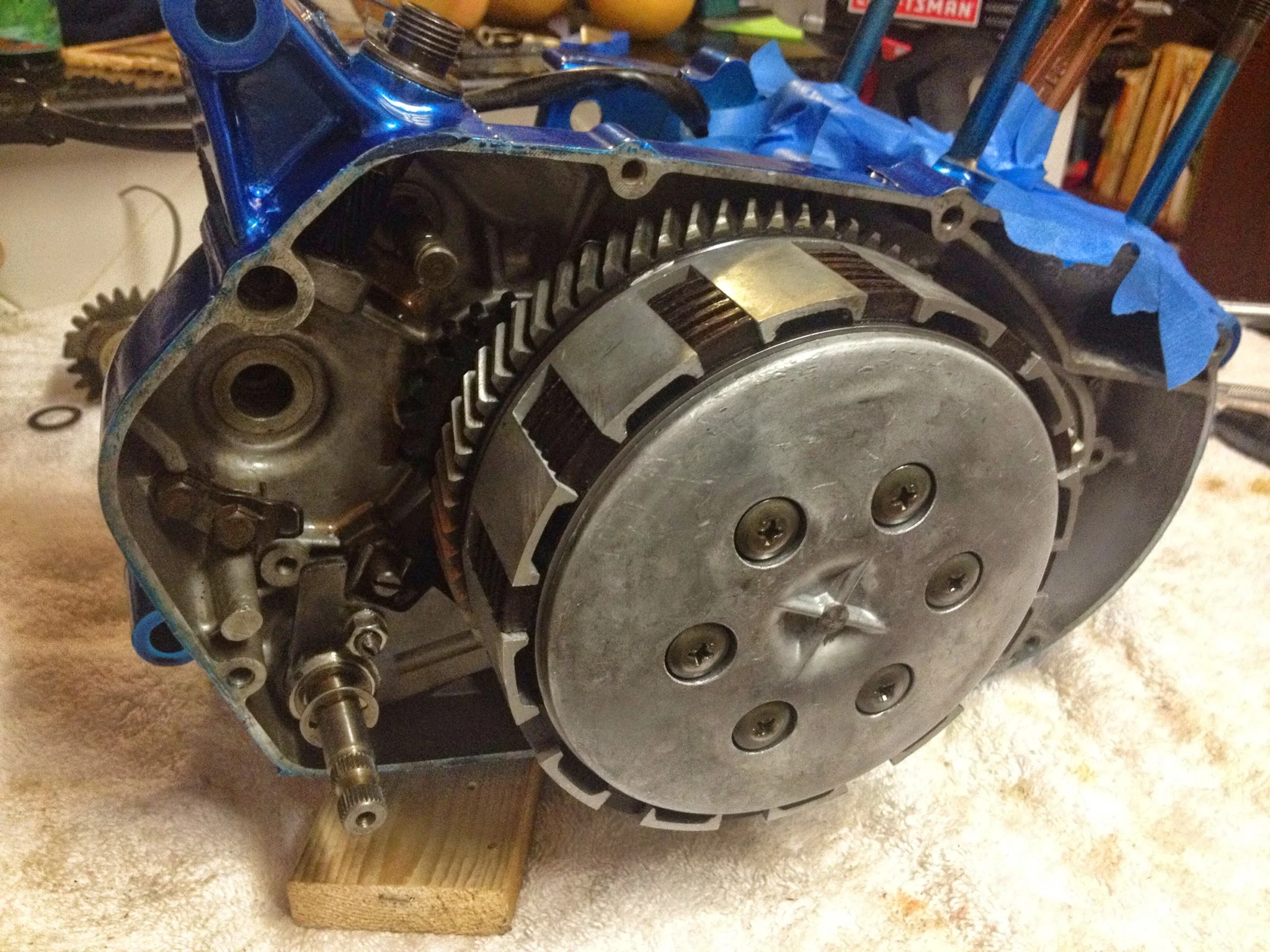
After getting the engine all bolted together I put it in the frame.
The frame...
I tried bolting a YZ426 to the frame. I tried putting YZ80 forks in the original triples. Finally i settled on doing what I originally wanted to do- Bolt a TW200 front end on.
A guy on ebay was selling a late model front end with disc brake....forks, triple trees, wheel, tire, caliper, everything i needed. It was too perfect of a deal. So a reasonable (as in not egregious) sum of money later, and i get 3 huge boxes at my door.
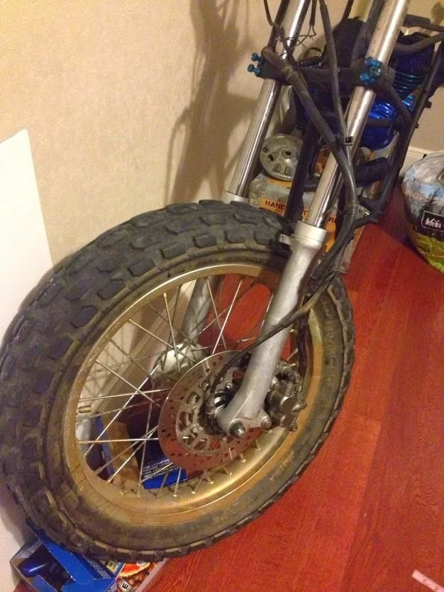
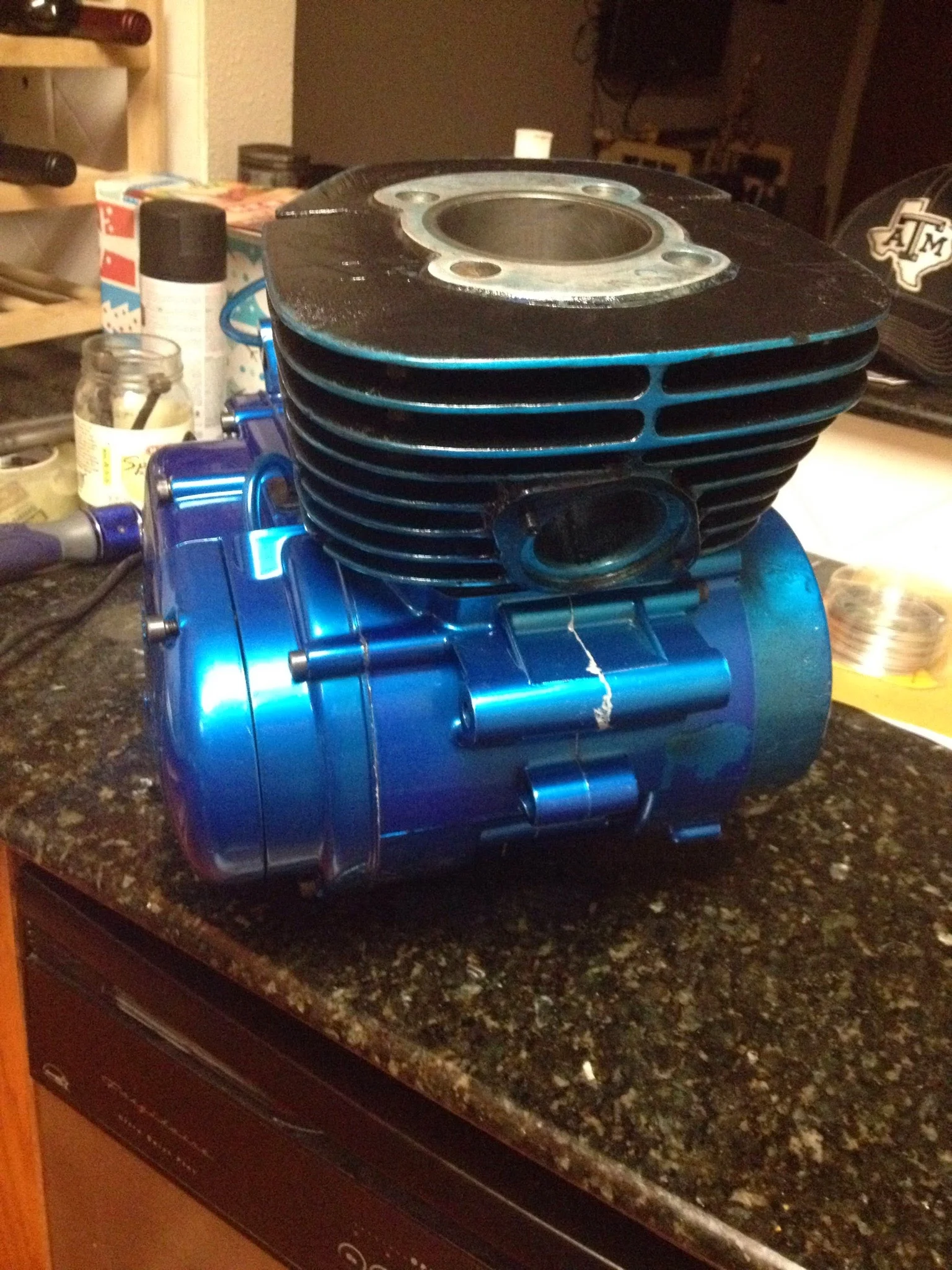
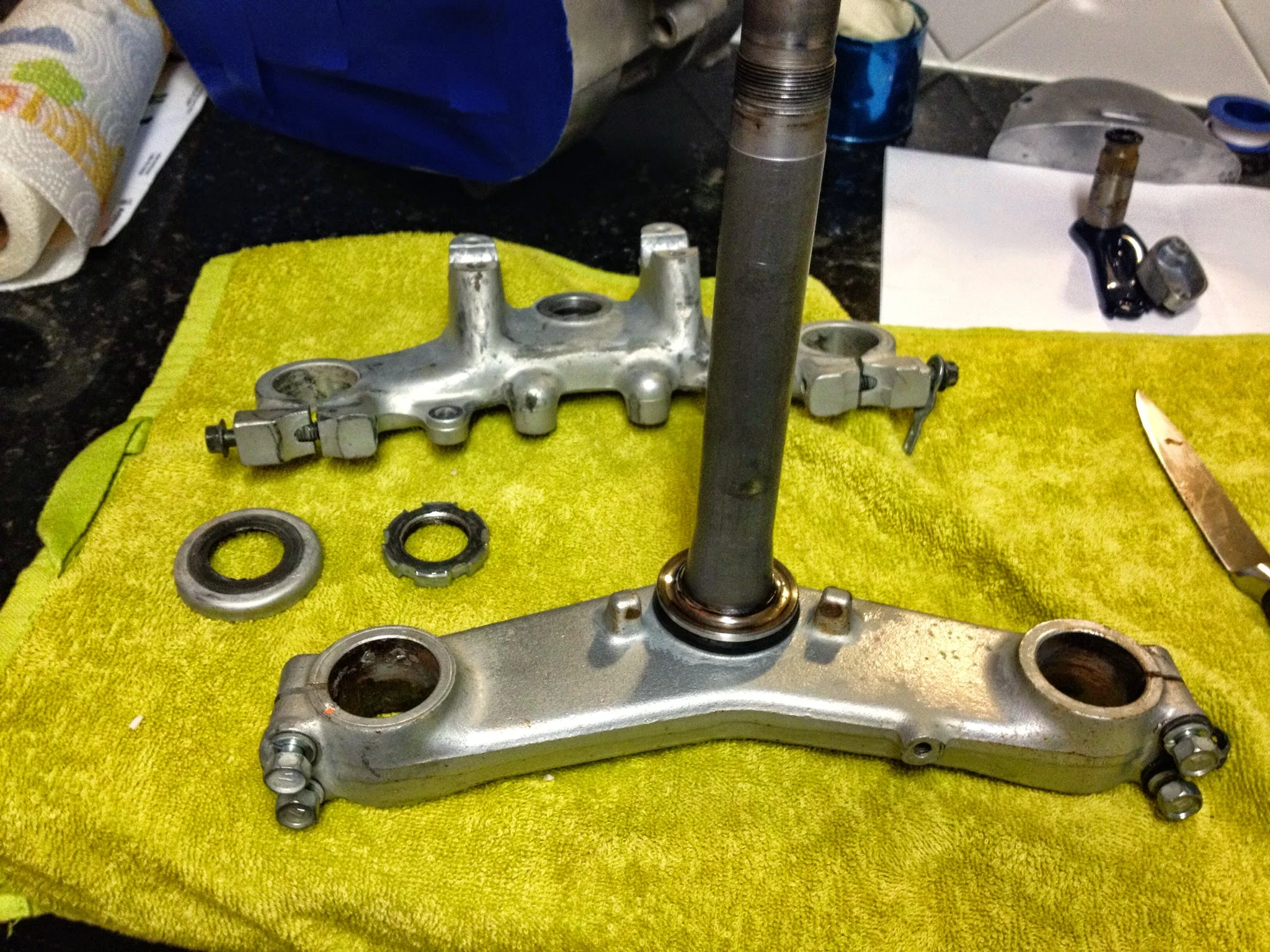
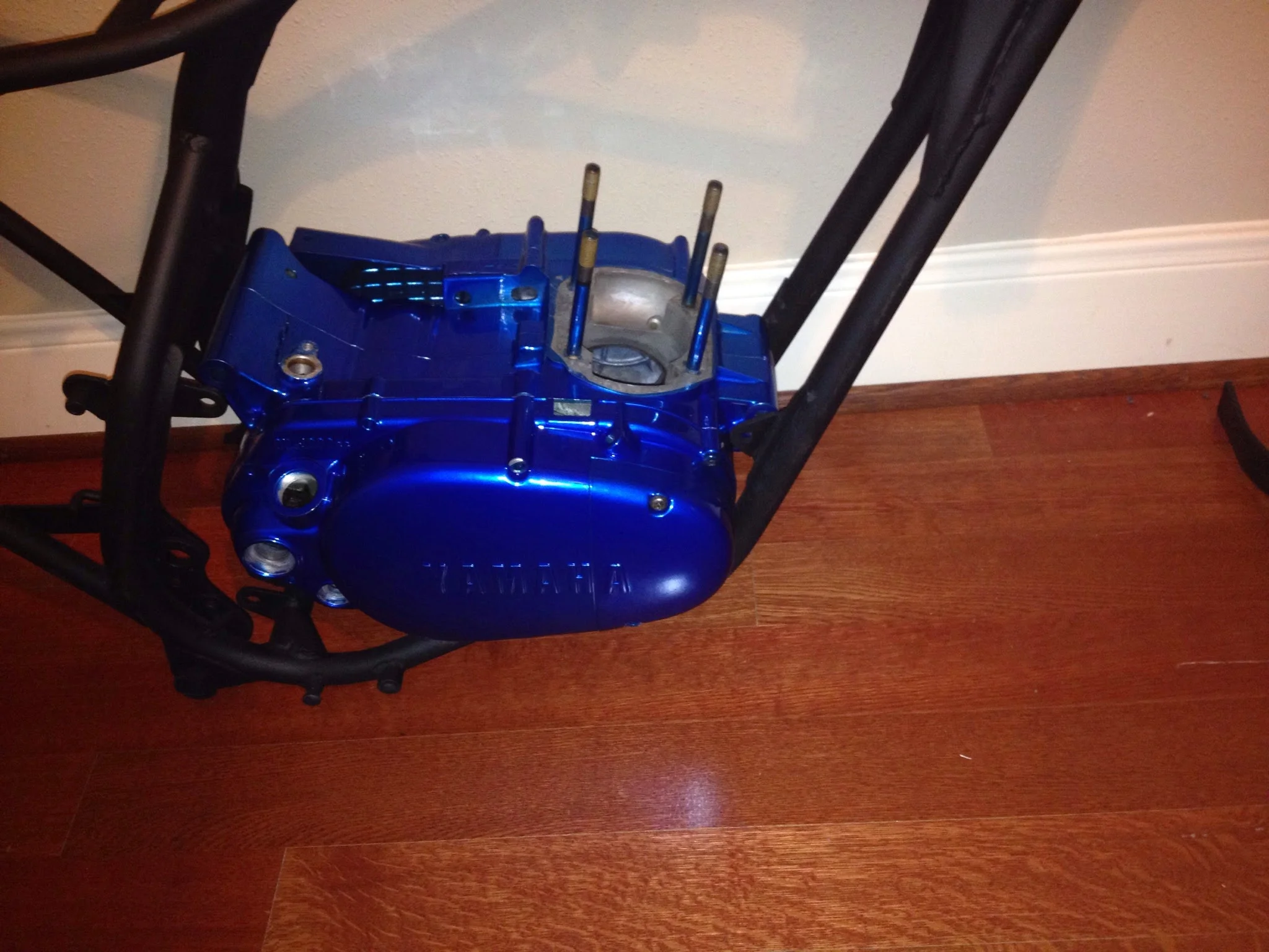
The bolt up is simple at the TW front end uses the archaic ball bearing style steering head bearings. I was able to get a tapered roller bearing in the upper race and use the standard ball bearings on the lower due to the DT1 frame having an uncommon dimension. SO there it sits. Flat black frame, TW200 front end, shiny blue motor ready to roar.
What I really needed to make it run- An exhaust pipe and a gas tank.
I found a DT175 tank, seat, and pipe on craigslist from an estate sale. The tank was full of old awful smelling gas, but nothing that couldn't be sloshed out. The seat doesn't fit the DT250 frame, and the exhaust pipe was just a bonus. It was never going to work .
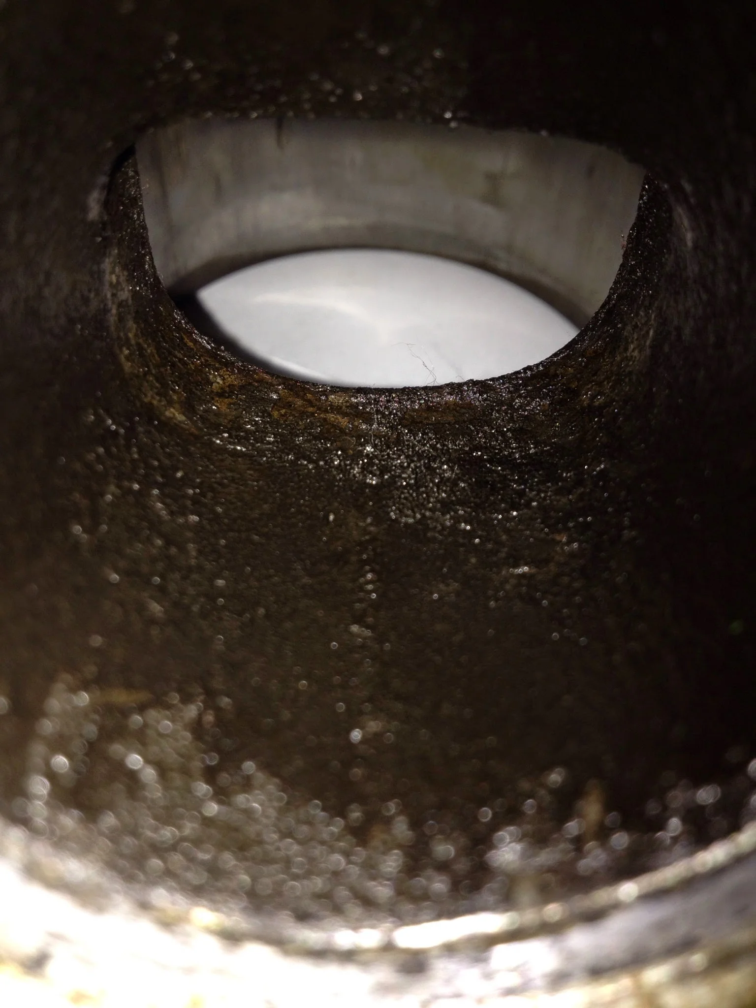
I did, however, find a mystery pipe on eBay. It looked like it'd fit an early DT250 and the seller said it was off a DT1. The bend as it exits the head was completely rusted through though. Holes everywhere. For $80 bucks i figured it was worth a shot though since the other chambers i've seen are regularly 200+
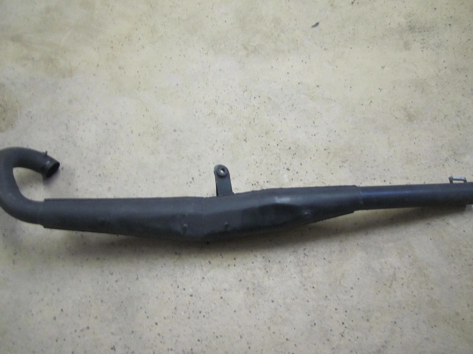
Pipe I found is identical to this one, except mine was swiss cheese on the left U bend.
And so accordingly, i needed to buy a welder. And if you're going to weld, you might as well TIG weld. My efforts were poor and ugly, but they hold the pipe together.
After taking some measurements, i felt confident that i could by a section of exhaust tubing and just slap it on the pipe.
A 2" diameter U bend with a 3" radius would be a perfect fit for the original. I found one on summitracing.com from Patriot and proceeded to cut and weld over the course of some weeks when i'd visit San Antonio on weekends.
Over Christmas, i decided it was time to make it run. So the pipe was welded together in final form, the gas tank was cleaned, petcock rebuilt, and 30:1 premix put in it. Then came time to fire.
4 or 5 kicks later and the engine roared to life and sounds amazing. Sounds and feels very smooth.
The premix was a crutch since the bike has an autolube system. Consequently, though, the pump wasn't working. (I later determined this to be a leaking seal under the primer wheel, at least i hope thats the problem)
But i did ride it around after putting the old chain on. A couple of immediate realizations
- That pipe is LOUD. especially when the throttle is opened up.
- This engine pulls much harder than the DT2
- Throttle response is instantaneous
- that front disc has awesome stopping power.
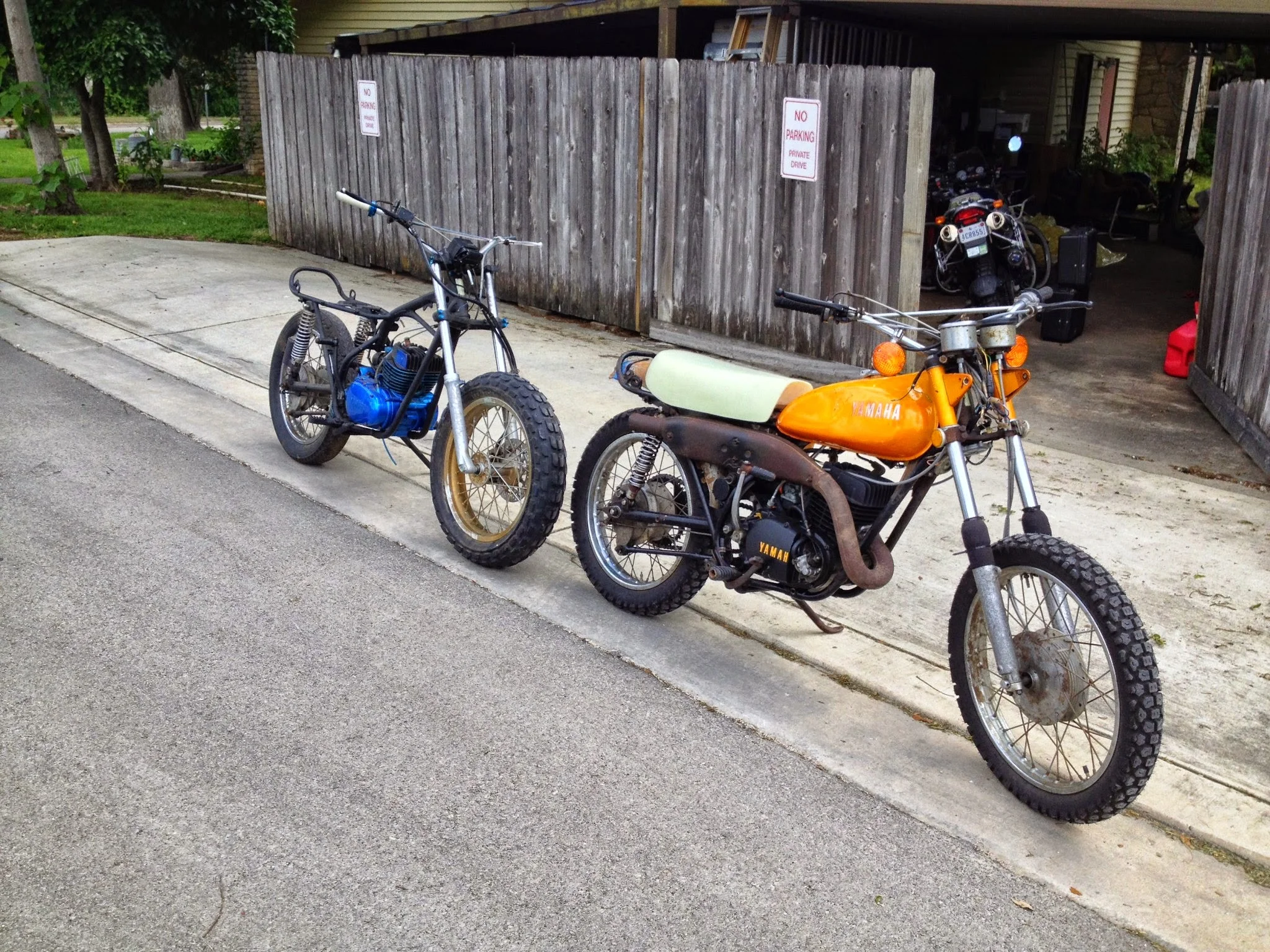
It still needs a lot. Need a proper tank. Need to make a mold of the seat pan and get a seat made. Need to fix that oil pump (seal is in the mail) Need to tighten up the steering head bearings. Need an air filter. Need to fix a broken bolt in the footpeg mount. Need rear shoes. Need a new chain.
It needs a lot...but it'll out run the DT2 as is!
Lost my head
Not sure why I pulled the engine out of the corner It has been sitting in for weeks. This evening I did, though.
I’ve had all that I need to complete assembly on the engine. What I’ve been waiting on is powder coating. Powder coating has been covered here before, and it’s not particularly hard but it is tedious. Clean the part, heat, clean the part, hang the part, electrify the part, coat the part, repeat, carry to oven, bake, take out, repeat the process, find time to keep the 1 gallon pancake compressor full of enough air to spray the powder. If I had a shop or better set up, it wouldn’t be such a pain in the ass.
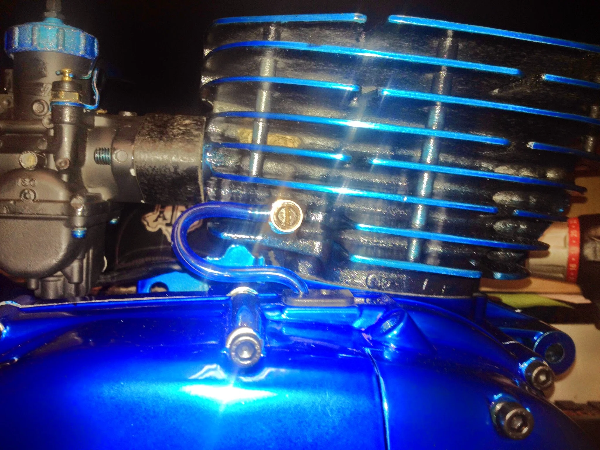
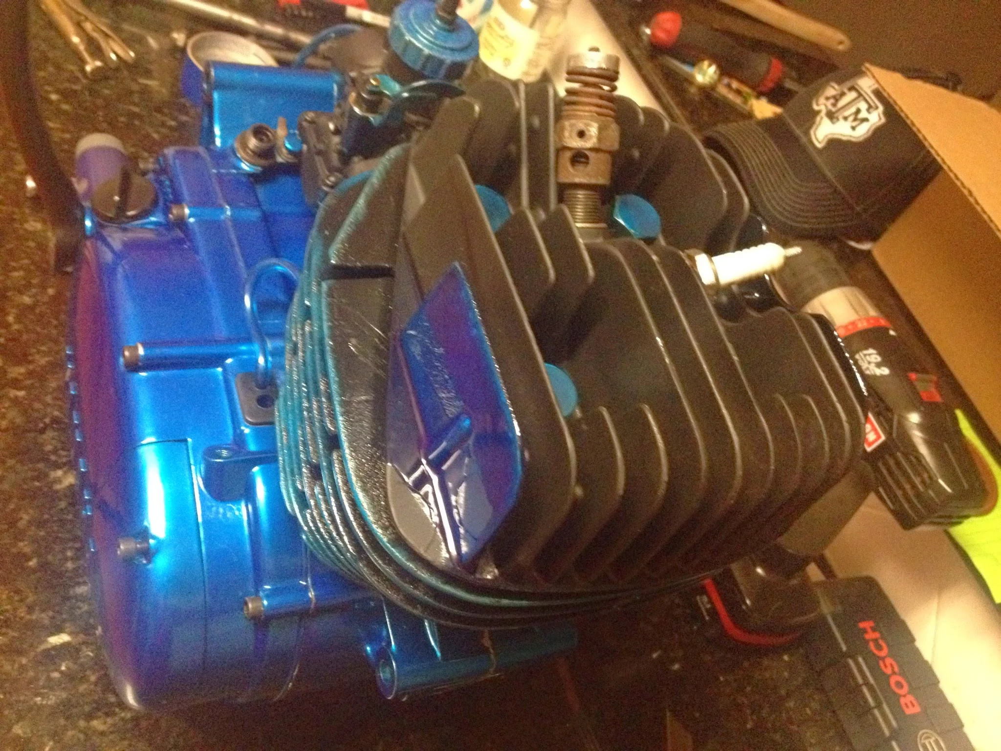
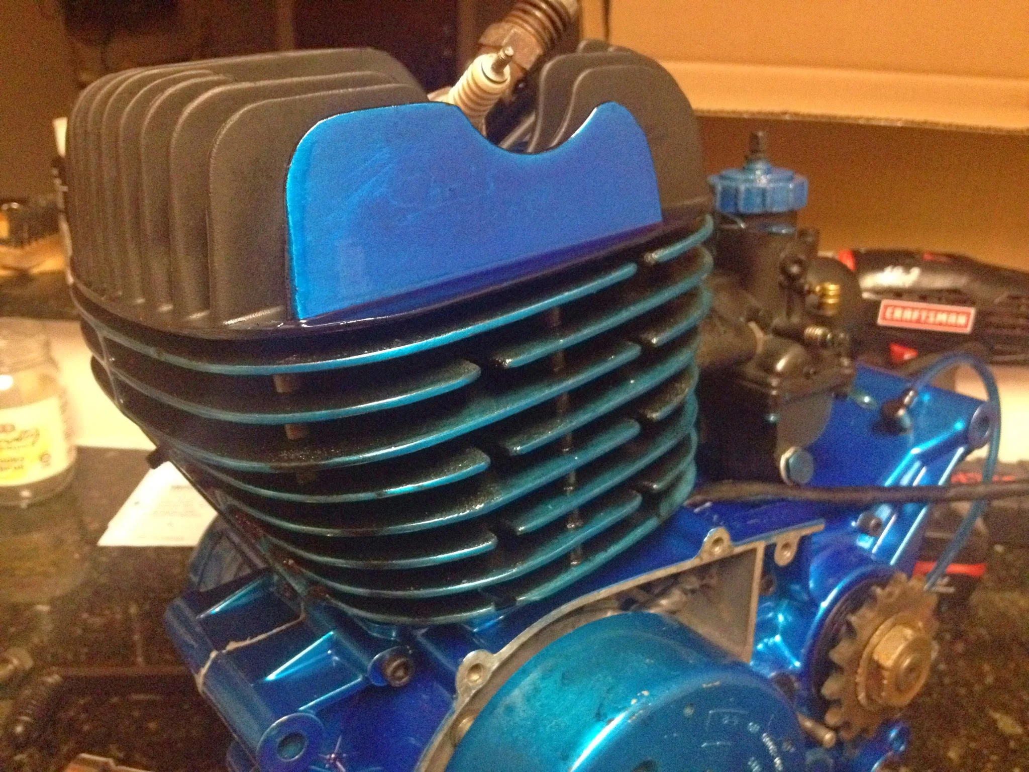
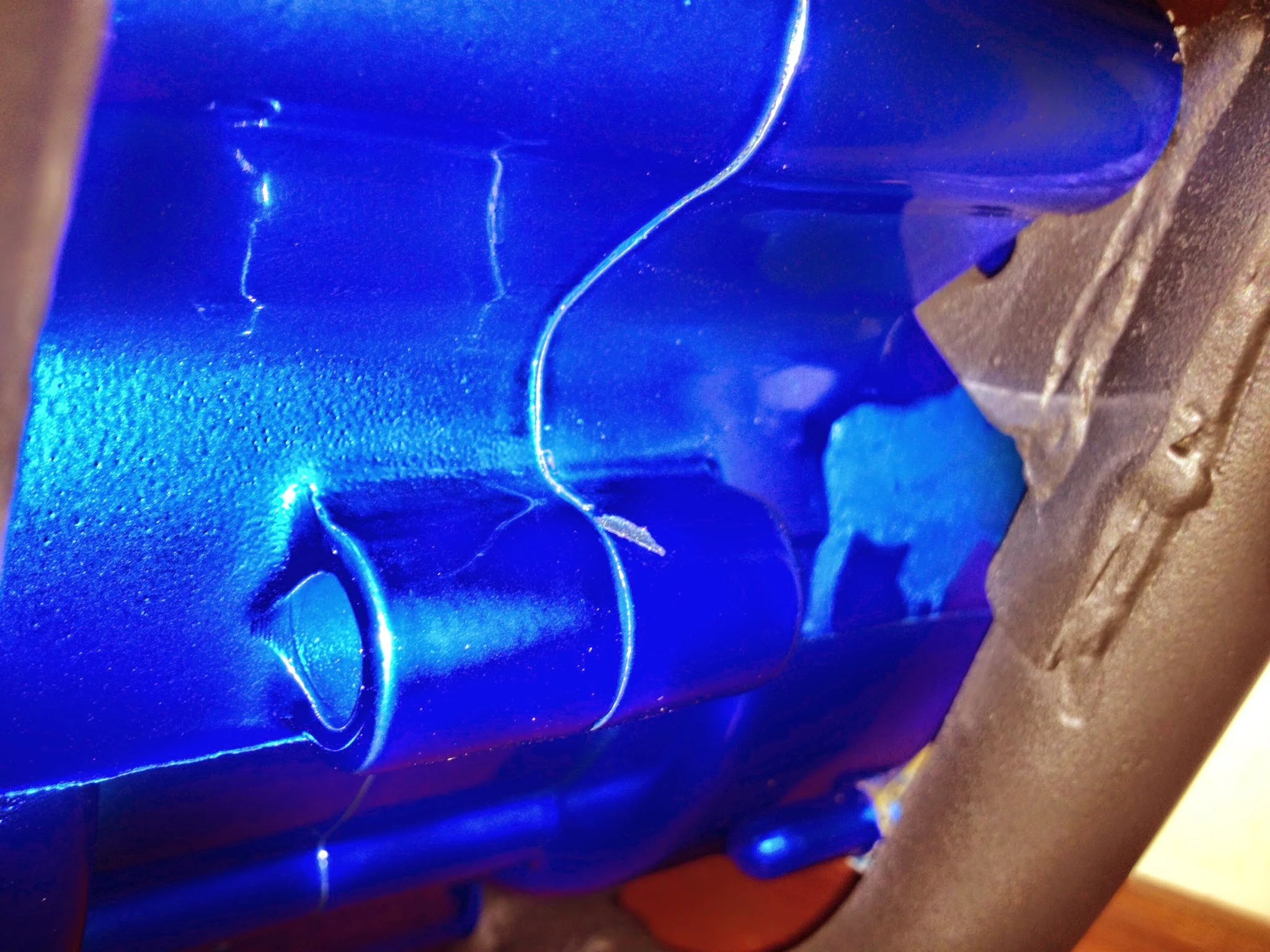
The color scheme for the head/cylinder came to me long ago. Back in the day, these used to be black with the paint sanded off the fins so that they were natural.
Okay, cool idea. I like contrast, but I also like blue.
So I sanded all the cooling fins with 80 and then 120 grit to expose a bright metal surface. The blue powder looks like crap on tarnished, rusty, stained metal. It only shows up well on a bright base. So sanding the fins was required.
Then I did a quick light powder. The electrostatic powder wanted to stick to the bare, freshly exposed metal fin edges anyway.
Bake.
Change powders, go plug in air compressor to refill
Tape off 2 fins on the head (because I always liked the idea of a blue fun on the head)
Spray the cylinder and the head flat black.
Gently wipe off ridges of the cylinder with a Swiffer cloth before baking. This exposes the blue powder coat that’d been baked on just prior.
Cook. Remove. Cool.
Remove tape from the cylinder head and tape off the freshly coated black. Spray the exposed fins blue.
Bake.
So that’s the sort of boring process of how powder coating happened. Took a few hours.
Here’s the more important mechanical details
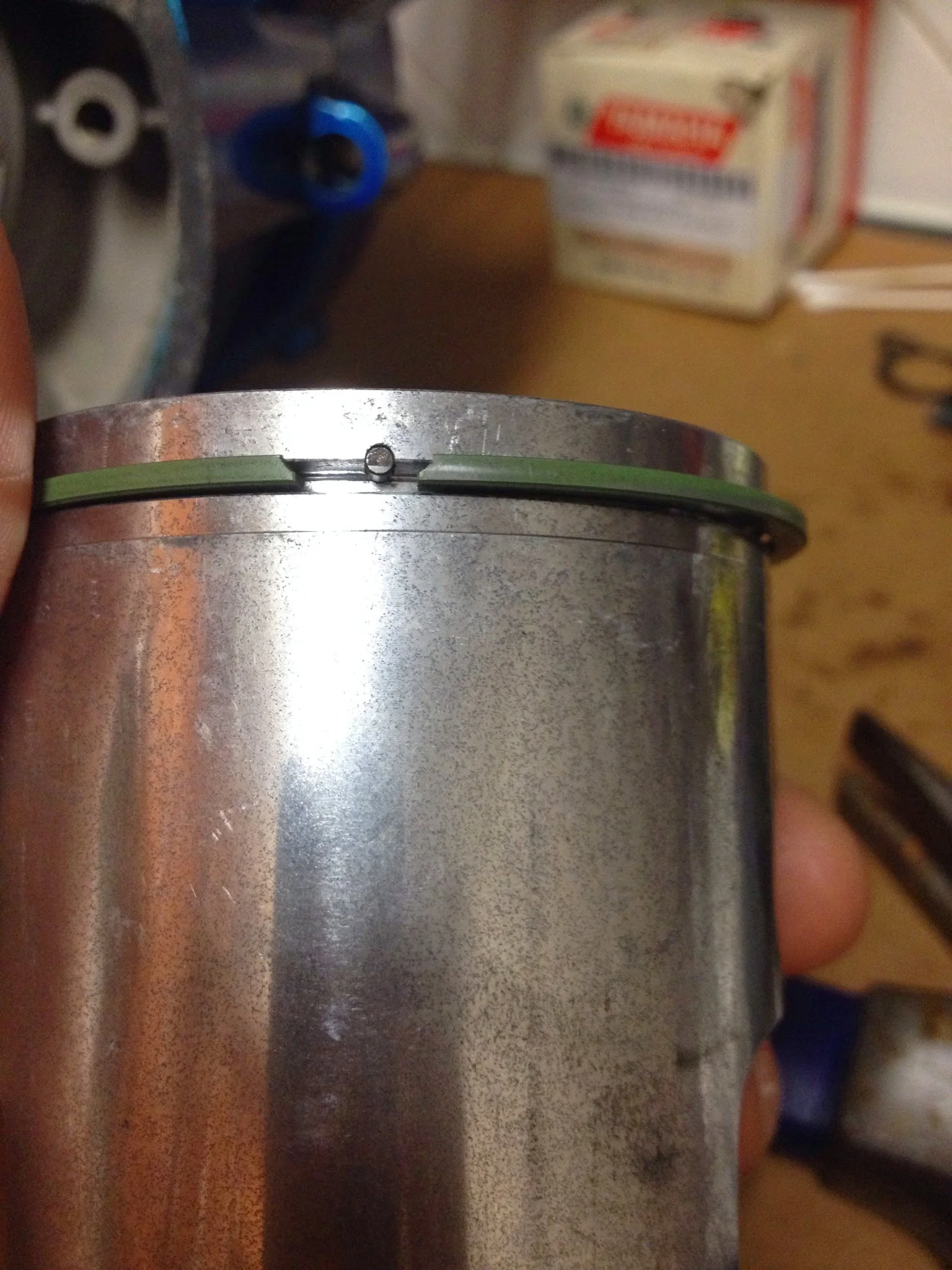
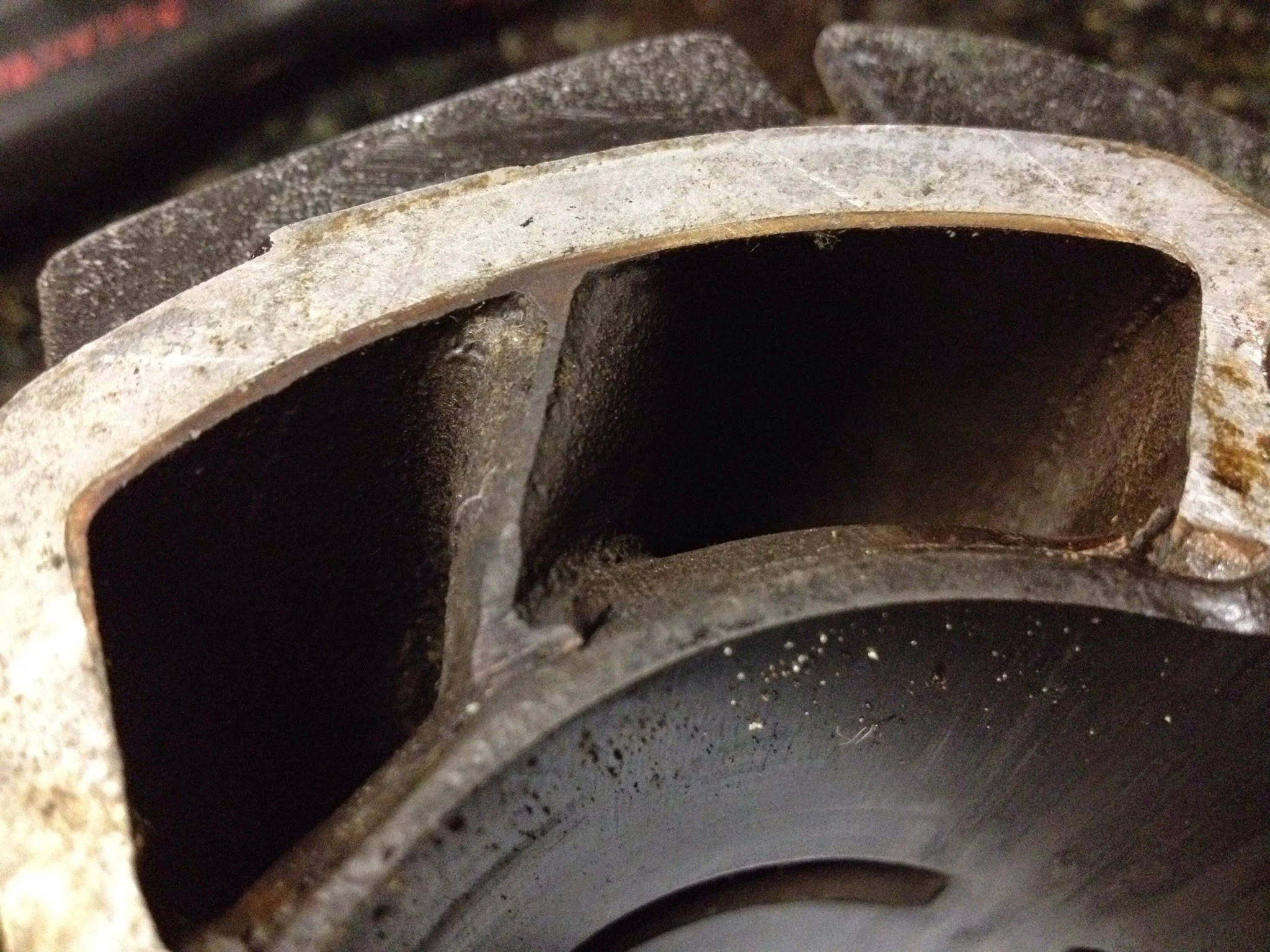
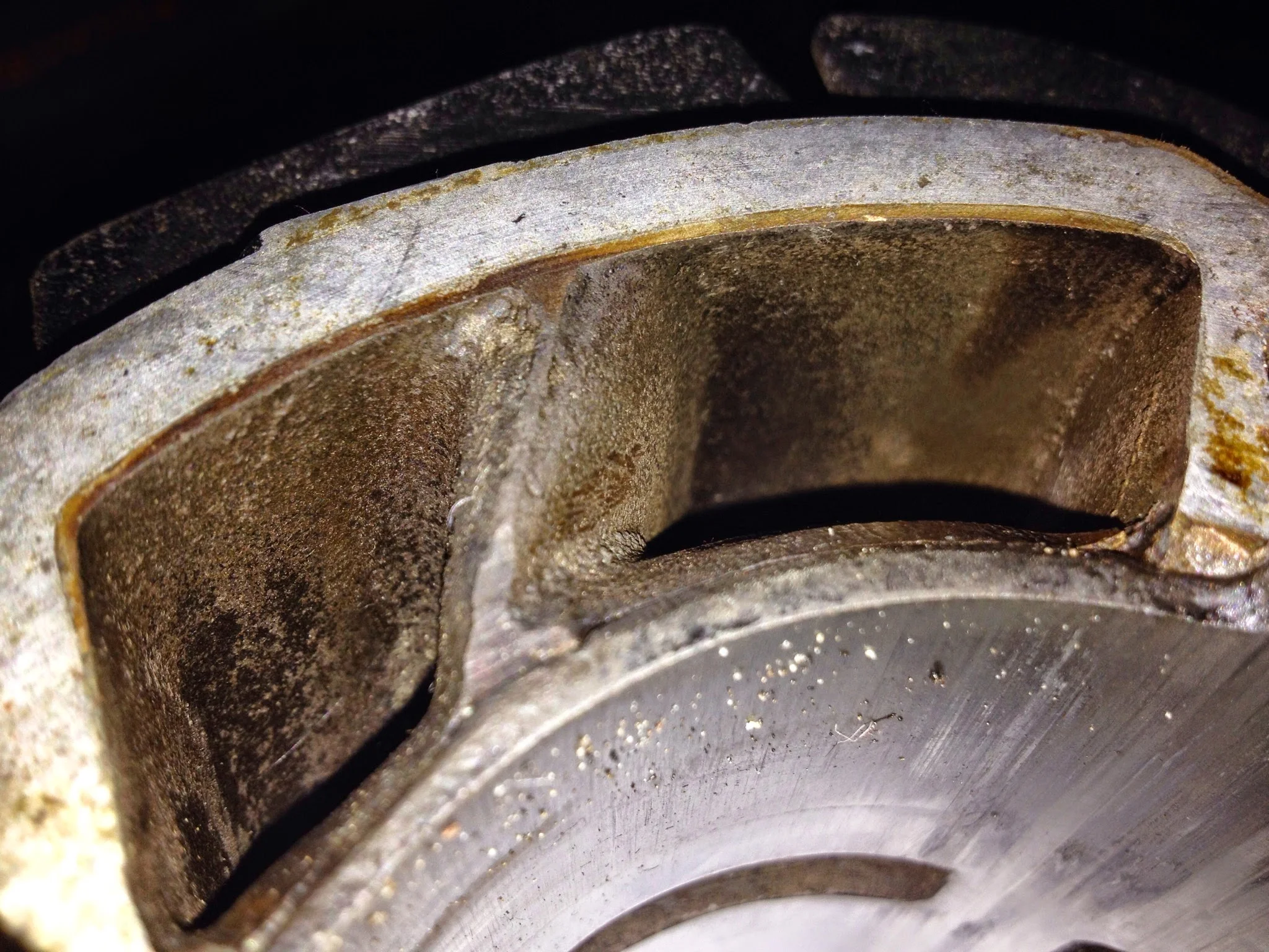
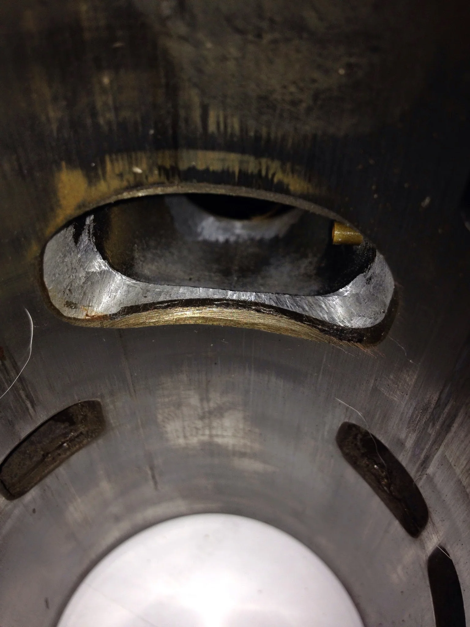
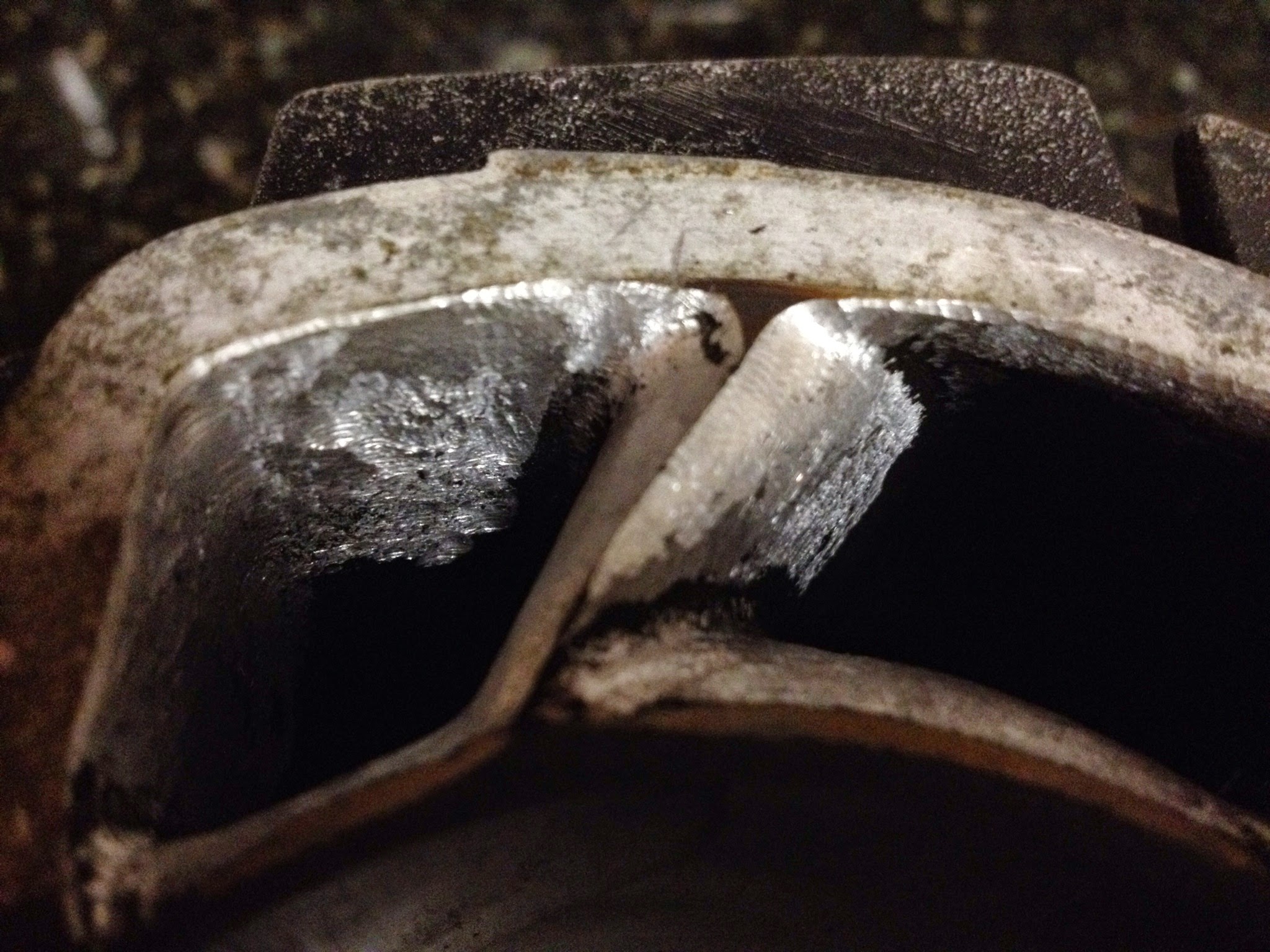
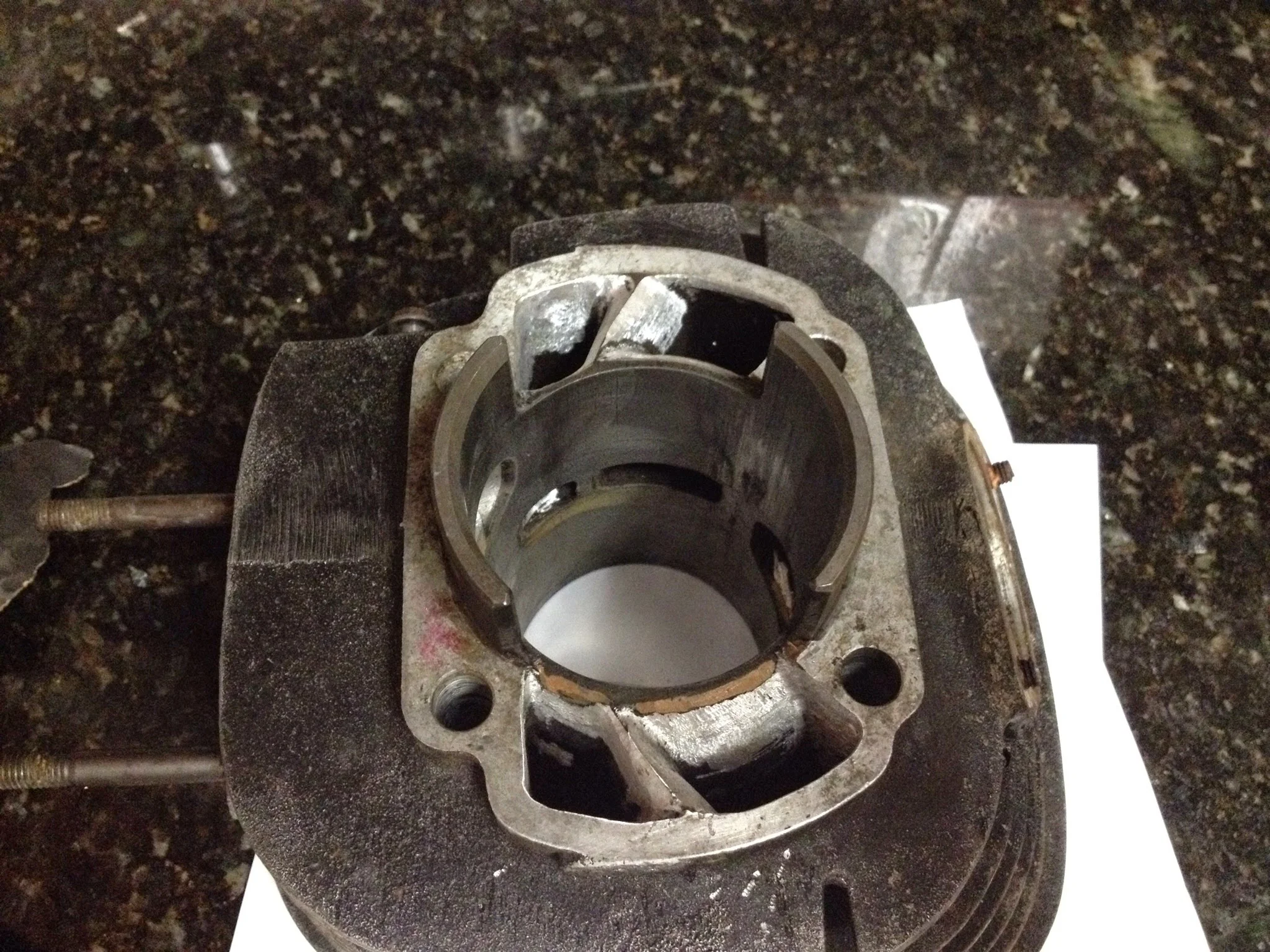
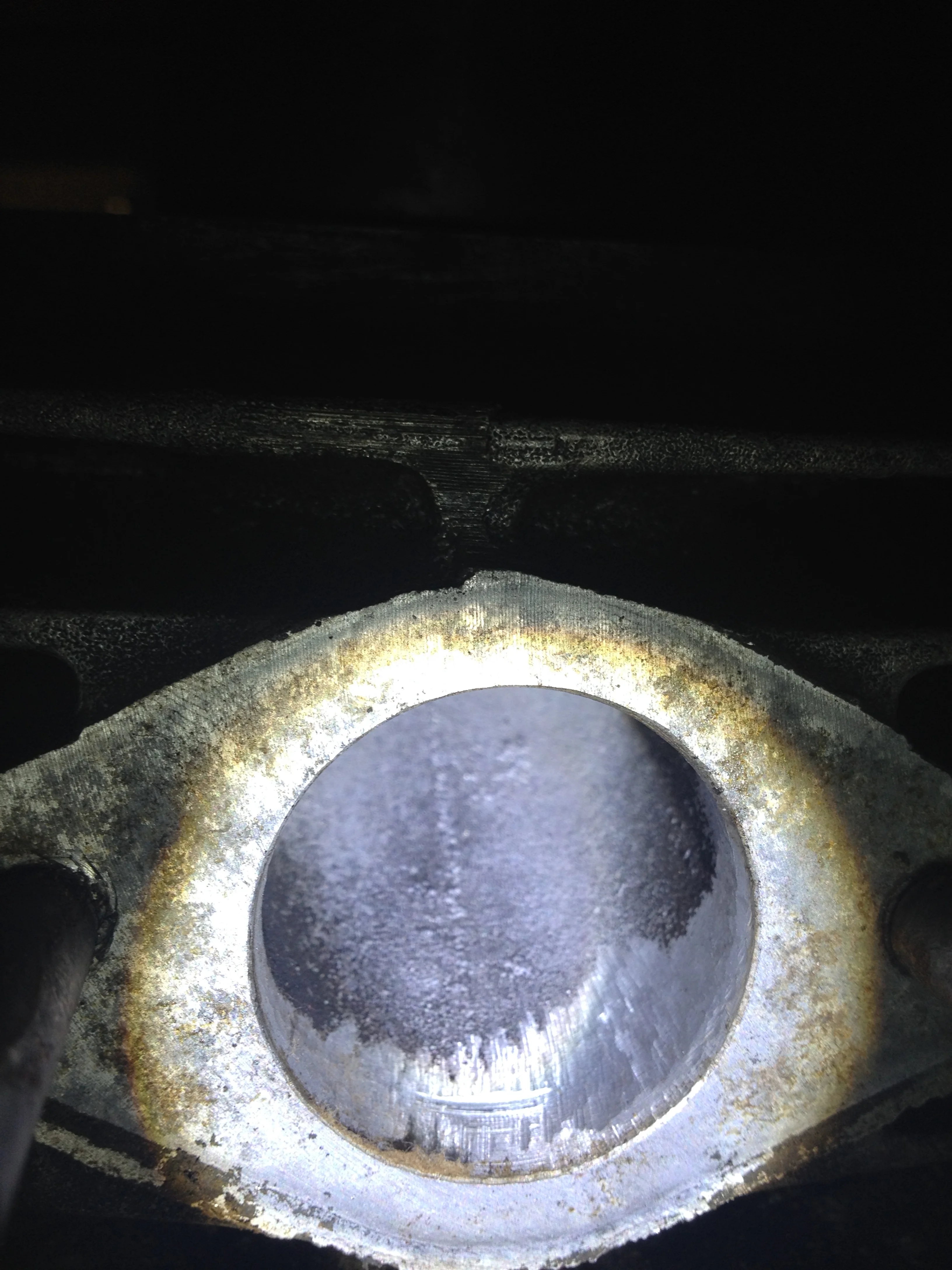
-After porting the cylinder and getting to bored, there were some sharp edges on the exhaust and transfer ports. Bad news for a single ring piston. Two-strokes are sort of notorious for breaking rings while running because they get hung up on a ridge.
I took a stone grinding wheel on the end of a Dremel and chamfered the transfer and exhaust ports. Intake port is never in contact with the piston ring but I was able to give it a 45 degree bevel where the port enters the steel cylinder.
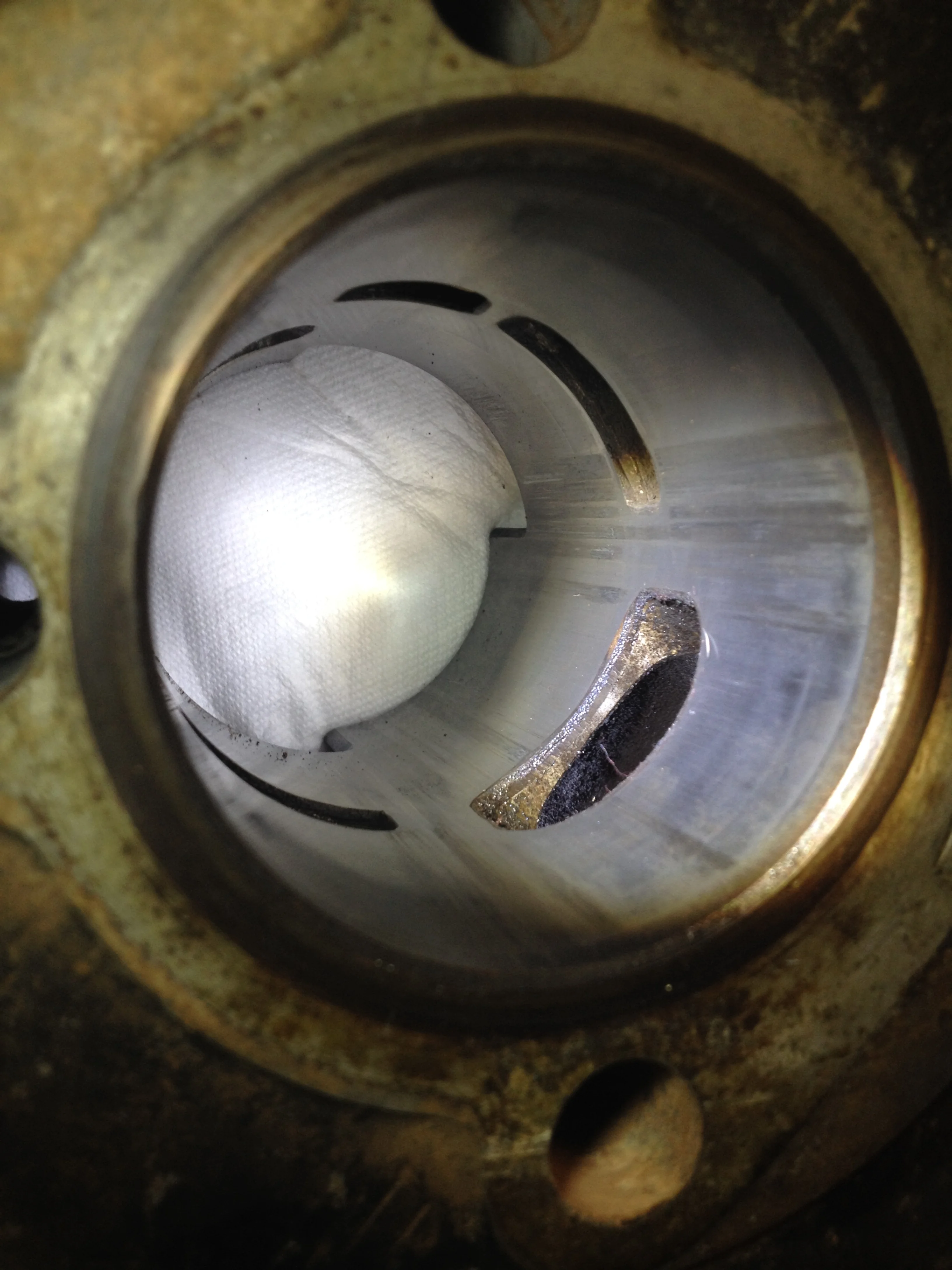
Motorcycles pistons are installed the opposite of cars: Piston goes on the rod first, and then you drop the cylinder on the piston. This makes compressing the ring or rings on a motorcycle really really important and a pain in the ass.
I put the ring on the piston way back when. Not any real trick to it, but I’m always afraid I’ll break the ring trying to get it on. It happens.
I put assembly lube on the upper crank bearing as well as on the wrist pin. When it was all lined up, the old wrist pin clips locked everything in securely.
All motorcycle cylinders I’ve come across have a huge bevel on the bottom to funnel the rings in to the cylinder. This helps, but I’ve still snapped rings. Having the engine on a kitchen countertop is a luxury compared to working on it in the frame at near-ground level. Having it close to eye level lets you get under the cylinder and see what’s happening. With proper alignment and some squeezing from fingers, the piston ring goes where it should, the cylinder slides on, and we’re one step closer.
I received a new head gasket in the gasket kit I bought, but I didn’t like the look of it compared to the old one. Both were copper, but the original was a tad bit thicker and had more material on the exhaust side.
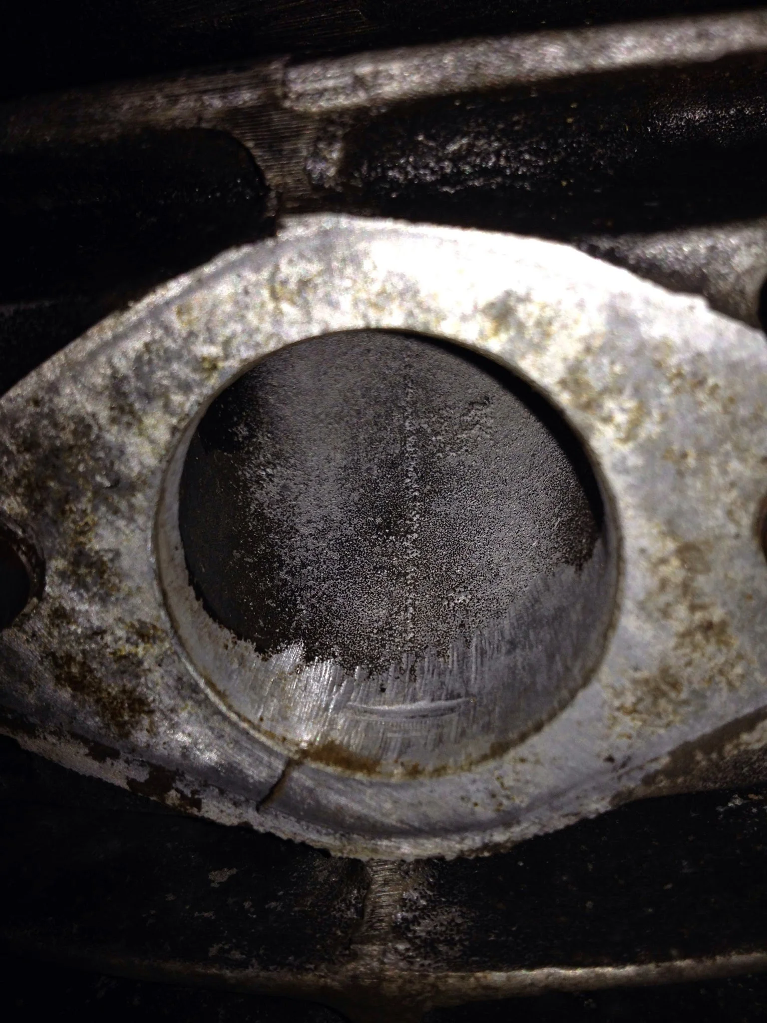
Carb Spacer went on the cylinder and I checked to see how well it lined up with the reworked port. It was 50% dead on, but some work with the die grinder and it was about 90% perfect. This should help get the most out of the intake port. If it translates to power, who knows?
I hooked up the oil supply line from the oil pump. The original tubing was in good shape, but I’m not sure this oil pump is going to perform. For kicks, I ordered some clear blue line so that it’d both look cool and let me see if oil is flowing. The plan for initial startup is pre-mix, regardless.
With the head off, I was able to see the piston so I figured it’d be as good a time as any to time the motor. Seeing the piston at top dead center isn’t at all required, but what the hell…
As the piston winds its way to the top of the cylinder, a set of adjustable points open which release stored electricity and causes the sparkplug to spark. This explodes the air/gas/oil that’s been squeezed to the top of the cylinder, and the explosion forces the piston downward. Process repeats. The rotation of the crankshaft spins the transmission which spins the wheel. Pretty neat.
Points are a contact breaker. Take your index finger and thumb and pinch them together. Those are points. When they’re closed, nothing happens. When you open them and your thumb and index finger break contact, that’s when the engine gets its spark. Timing (when this spark happens in the 360 degrees of the pistons’ travel) is really important. There are always marks and indicators to indicate where timing should be (roughly) but timing can be advanced/retarded based on tons of other variables. In later years, engineers would strap mechanical advance mechanism that would change timing with the rpm of the engine. Really awesome idea.
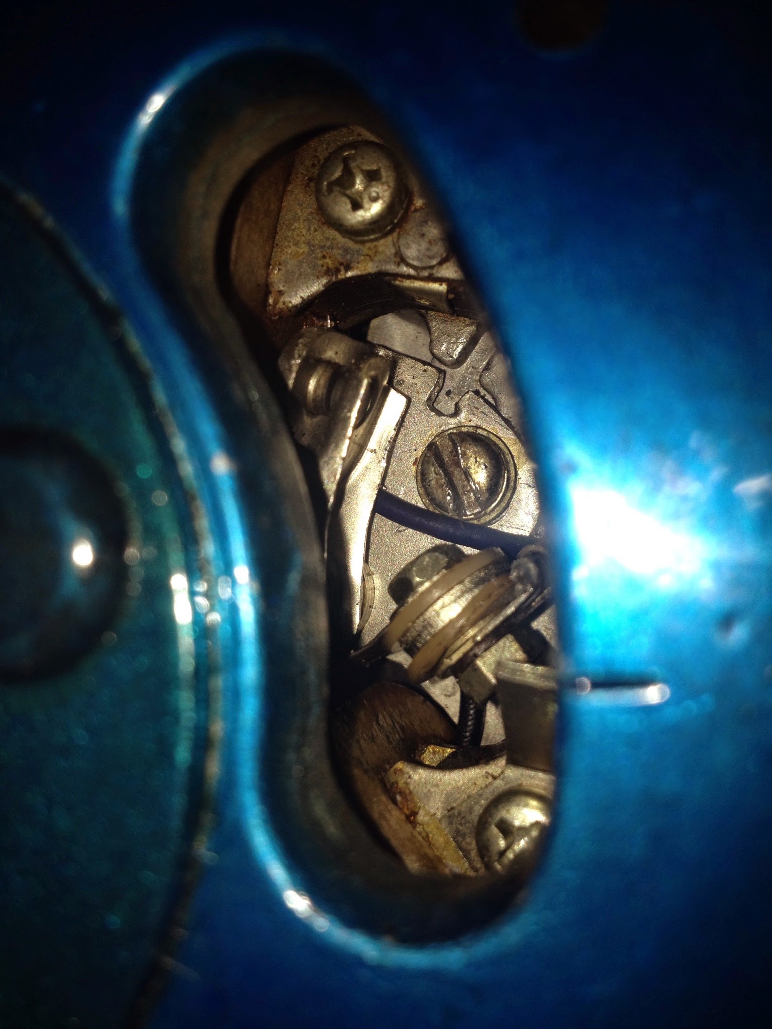
Blury notch on the blue flywheel is the timing mark. It is supposed to line up with that metal tab that's held in with a phillips screw. The points are open here. They're adjusted by loosening the straight screw
For this bike…not really important. There’s a mark on the flywheel, there’s a mark on the stator. The points should be opening at that point. The trick is adjusting the points themselves. I got it locked in where I want, or near enough. I’m confident it’ll fire without adjustment.
I bolted the head on and kicked it over a few times to make sure everything was spinning and that I had compression. I did, but only when I kicked it fast (should have compression when kicked slow) So I tried to tighten the head down some more and I noticed it that the bolts were tight, but there was about 1/16th inch of space that the head could wobble up and down. It wasn’t getting tight.
Head bolts. Now ft 100% more washer!
Then I remembered there are washers that go under the head bolts.
That proved to fix the compression problem.
Compression. This thing has it. Lots of it. Or maybe it’s in my head. It was loud, forceful, and smelled like assembly lubricant though. It was magic.
I’m as confident in my skills as the next guy, but this think was broken down to its pieces and has been that way for nearly a year.
Will it start? No doubt.
Will it run? We’ll see. I have some concerns about the port timing, but I didn’t change any of it so it should work out.
It’s sitting back in the corner where it came from earlier…but now it’s all together.
Need intake spacer gaskets, carb o-ring, and a decompression valve (or a bolt) for the head. I need 6 screws to put the clutch side cases on, and this thing is going back in a frame.
Big news on the frame…is USPS ever gets here, I’ll tell you about it…
Boring
After getting word from Harold that the cylinder would need to be bored .50mm over (or the 2nd over) I started sourcing a piston and a ring/rings.
Yamaha switched to a reed valve induction system in 72 which made more power and was more efficient presumably (they've been using reeds ever since). Pistons for those engines are easy to find…like order-them-in-a-catalog easy.
DT1 pistons…not hard to find, but they’re the order-them--on-ebay kind of not hard.
Found a decent deal after little to no searching; a DT1MX Piston. When I bought it, I knew there is a different piston ring configuration than the DT1E (what I have)
I learned after getting the piston and looking at it that the skirt is also much shorter (this will affect port timing) and that the piston is a good few ounces heavier than the old DT1 piston.
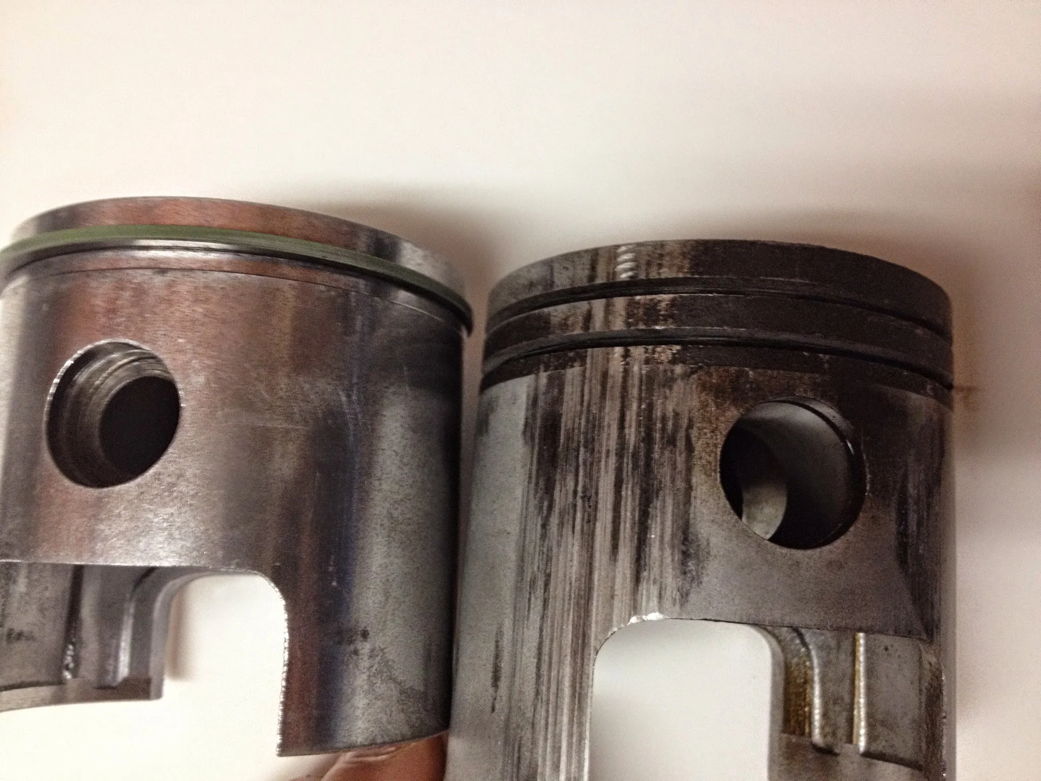
Though thinking on it now, the old piston was gouged, had another ring grove, and lived a hard life in its latter years. It’ll find its way to a book shelf or a desk to lead a less stressful life…
There’s something really reassuring about going to a place of business that’s named after a man and actually talking to that man. This was the case at Harold’s Machine Shop. It was a 2 man operation in Richmond, Tx as best I could tell. I think is comrade was named Donnie. I gave him the piston and ring so he could do the finish work and I picked up the cylinder the next day.
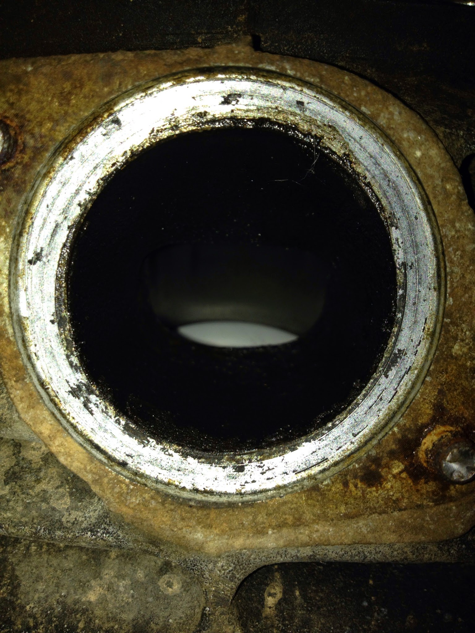
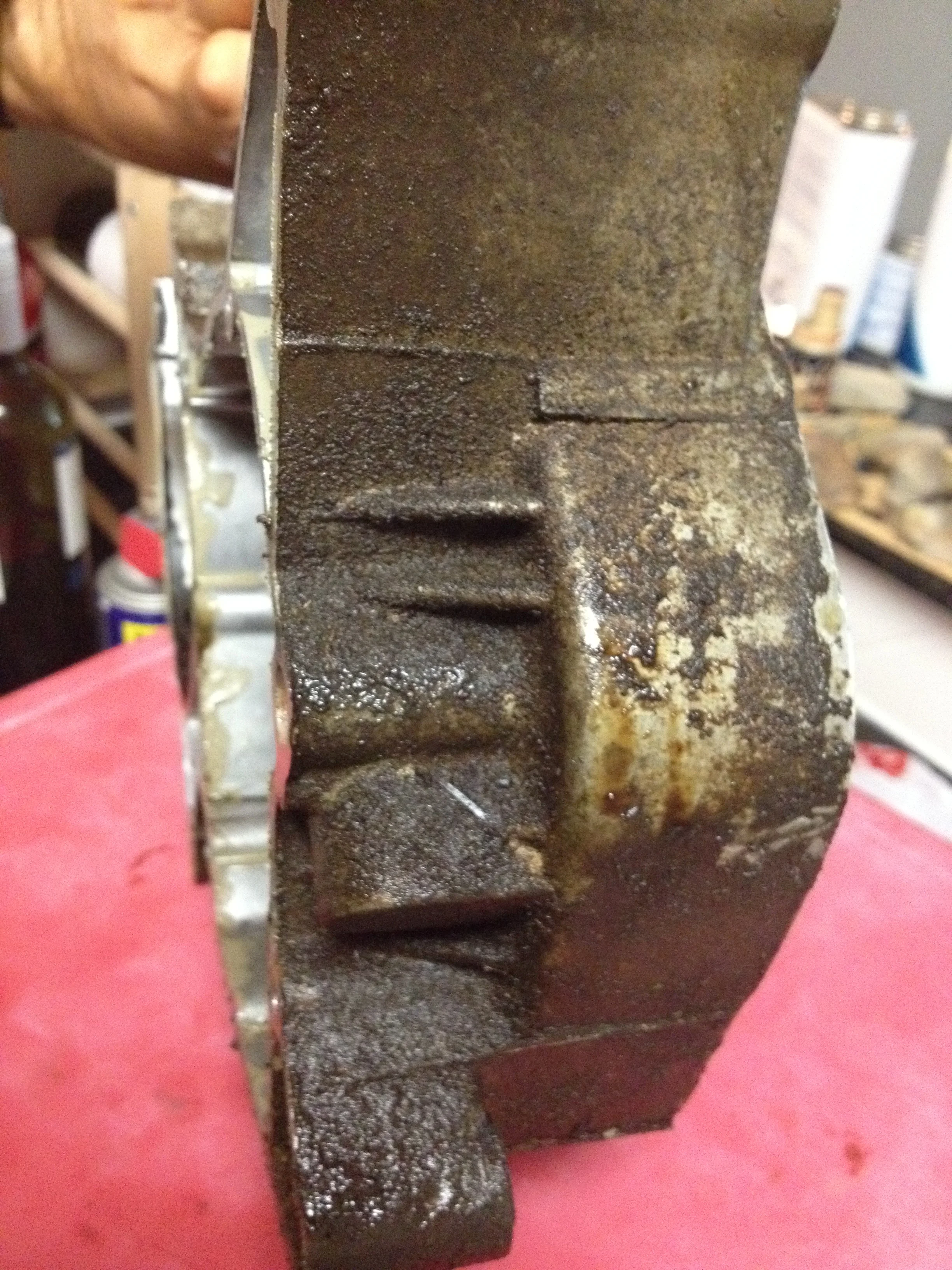
Steel liner needs to be filed to smooth the transition between ports/cylinder wall.
I’m a little sad that it didn’t come back hot tanked or cleaned, but for $64 I have no room for complaint.
I was unable to find what the proper ring gap should be. I feel like the gap might be large, but can’t say for certain without the data. We’ll see how it runs…
Somewhere in the time before, after, or while the cylinder was in the shop, I slowly collected my pieces from USPS. A tachometer drive gear, a shift shaft washer, a tiny oil pressure spring and a 5/64ths diameter ball bearing. A rubber “oil pipe holder” and a grommet for stator wires.
I’m happy to say that it was a day ago when I put the clutch side engine cover on with black oxide allen screws and plan to never open it again. (But I’m a realist. I know it’ll be open again…)
Gear on bottom left is Kickstarter. Didn't look right. Should have known...
How we fix torn gaskets.
The gasket kits for these engines, or maybe just the ones I’ve gotten (because this happened with the DT2) are some odd sort of deformed. Not enough to matter from a functional standpoint, but just enough to put weird stress on the gasket at certain bends.
I put the kickstarter shaft in (thinking that it was all too easy) and buttoned the whole case up. After kicking it a few times, I noticed the kick starter shaft was installed wrong. Goody. So off the side over comes, I re-set the kick starter shaft (not rocket science, but a return spring has to catch on a certain knob) and upon trying to put the cover back on…tore the gasket. I’m thinking it’s nothing Motoseal can’t fix.
I was going to just stick the autolube system on (oil pump) and let it ride….but it kept me awake at night not knowing if it was full of sludge or solidified castor oil or what. So I took it apart….
Last time I took one apart (DT2) I ruined it.
2 Stroke oil pump. No need to premix as long as you have faith...
These bikes (all bike, really) have road maps..exploded part diagrams for every little system showing what part goes where, what part number it is and how it interacts with other things around it. It’s like a mechanical, 3d paint-by-number.
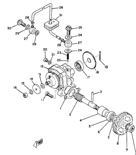
Part 23 does not exist on earth. Also note #12- a screw. Behind those 4 screws is the insanity.
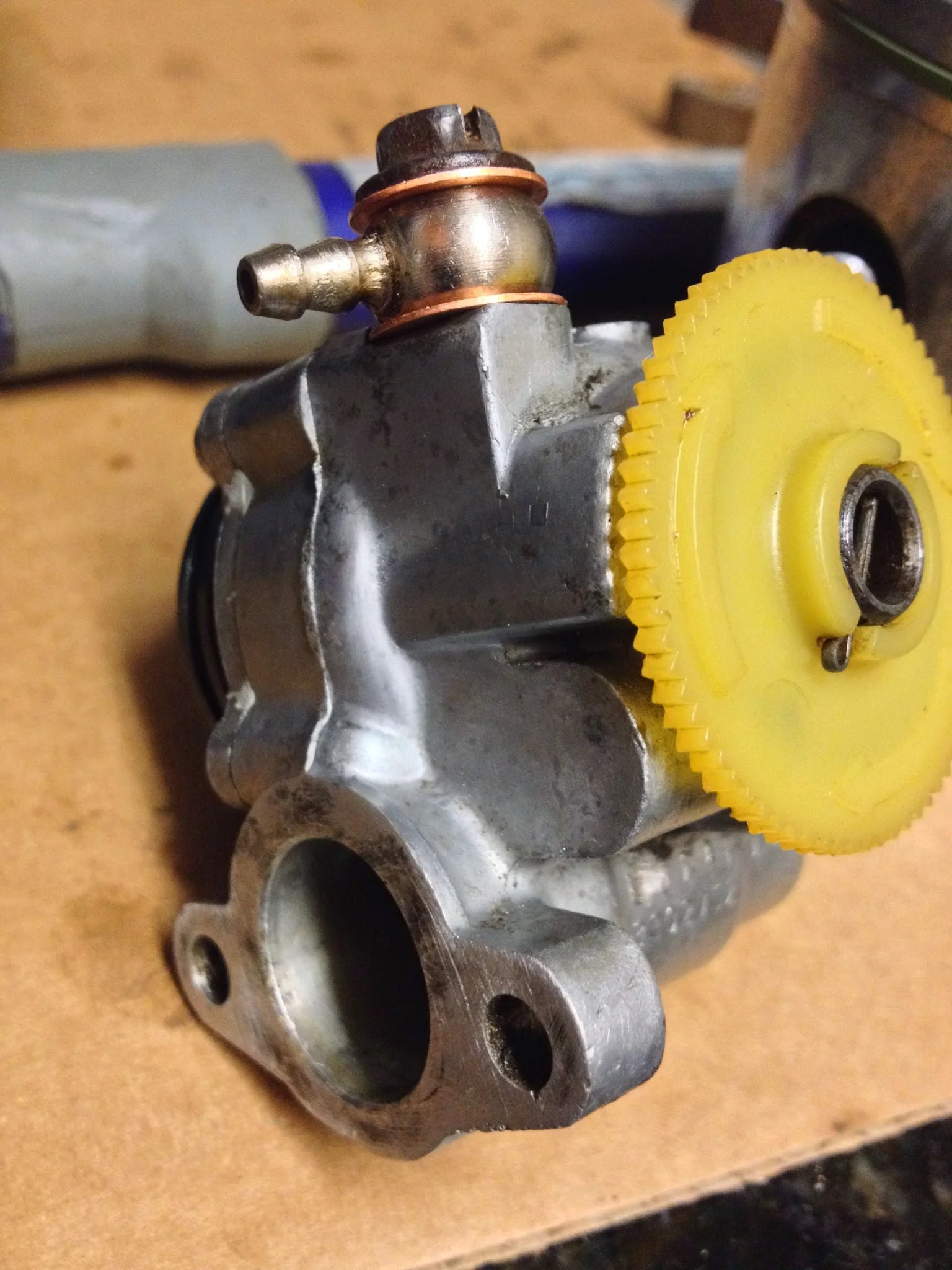
The oil pump is an exception. There’s no diagram showing what’s in the pump. It’s some gears, microscopic (honestly, damn near…) springs, some seals, and a crazy array of different sized washers of different thickness that are of critical importance.
I ended up being glad I took it apart because there was some crap in there…but it was a very painstaking time. SO much so that I took 0 pictures. As a plus, though…I lost the little spring and the directional gear that ratchets on them. BUT I found the springs. And managed to get the gear back on. Doesn’t sound hard…but it was an amazing feat. I’d read from a few people “If the gear comes off (off the spring loaded pins) throw the pump away and find another one.”
Feel pretty good it’ll pump oil…I modified the lower banjo bolt since they don’t make and it’s impossible to find a spring that goes in it. Drilled the hollow bolt out a tiny bit and was able to get a later model spring (from a 76 DT250 oil pump) to fit. No idea if it’ll operate correctly so careful testing will be done before firing.
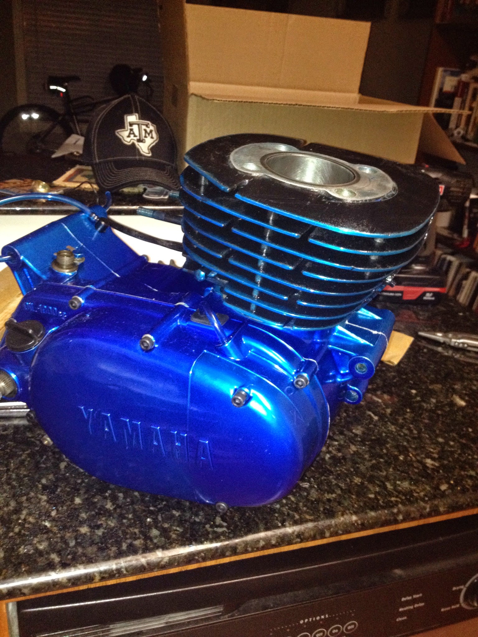
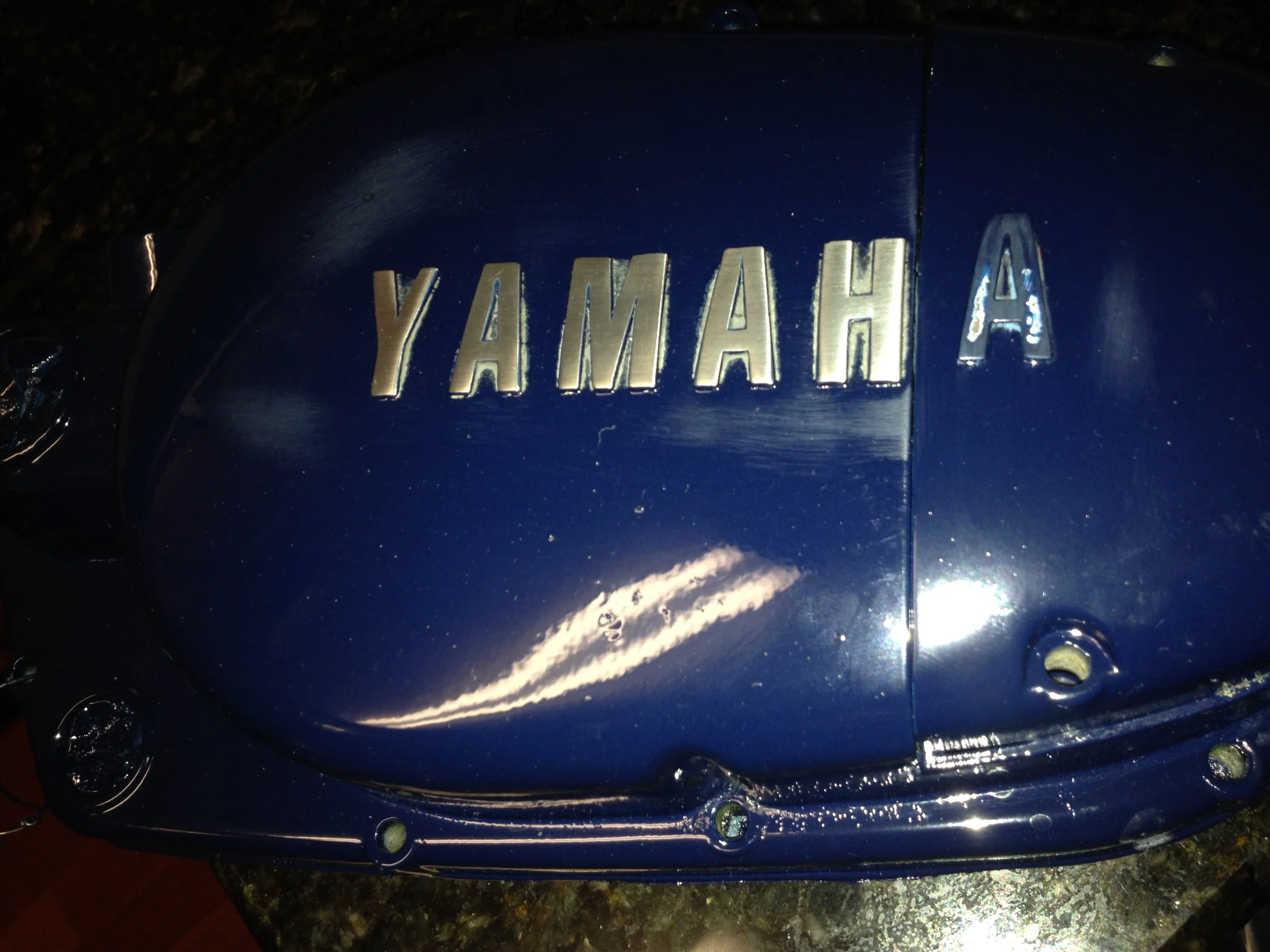
Next steps- Black letter the “YAMAHA” on both sides
Port and polish the cylinder, polish the head. (tools are in the mail. Doing it by hand got old fast.)
Powder coat the cylinder and head
Bolt it together.
The end? Don’t know what to do after that…
Sealing it up.
I do feel pretty good about this engine though. As far as tolerances, parts, function, and the fact that literally no stone (or bearing) has gone unturned.
And in the end, it’ll amount to a loss of money because no one will buy it, I don’t have anywhere to ride it, the “bill of sale” is some scribbles in red ink from a 14 year old, and I don’t really know what to do with it…
But it sure is a lot of fun building it.
Should probably take up fly fishing instead.
Portal 2
Some weeks ago I started porting the cylinder on the DT1. The last time I ported a motorcycle cylinder (head) I was maybe 16 and the bike was a Honda Z50. (it was an overhead cam engine, so the intake and exhaust ports were on the actual cylinder head. On two strokes, the ports are built in to the cylinder itself. The 2 stroke cylinder head is nothing more than an aluminum chunk with a combustion chamber, nothing else) I also had plans to supercharge that bike with a Coleman battery powered air pump and PVC pipe adapters.
Porting is the enlarging, smoothing, and streamlining of intake and exhaust ports. Sometimes it’s called porting and polishing (polishing is what it sounds like) the idea is that smoother, hand shaped ports allow air flow to move in greater volumes with less restrictions. The result- more power. Or, if you’re from East Texas, more “pahhrR.”
I’ve learned most of everything mechanical through reading, studying, looking at pictures and most of all by actually doing it and messing up. But my philosophy on life has changed, and that’s transferred over in my approach to this porting project. My philosophy now is take baby steps forward instead of a huge leap. And as much as possible…don’t overdo things.
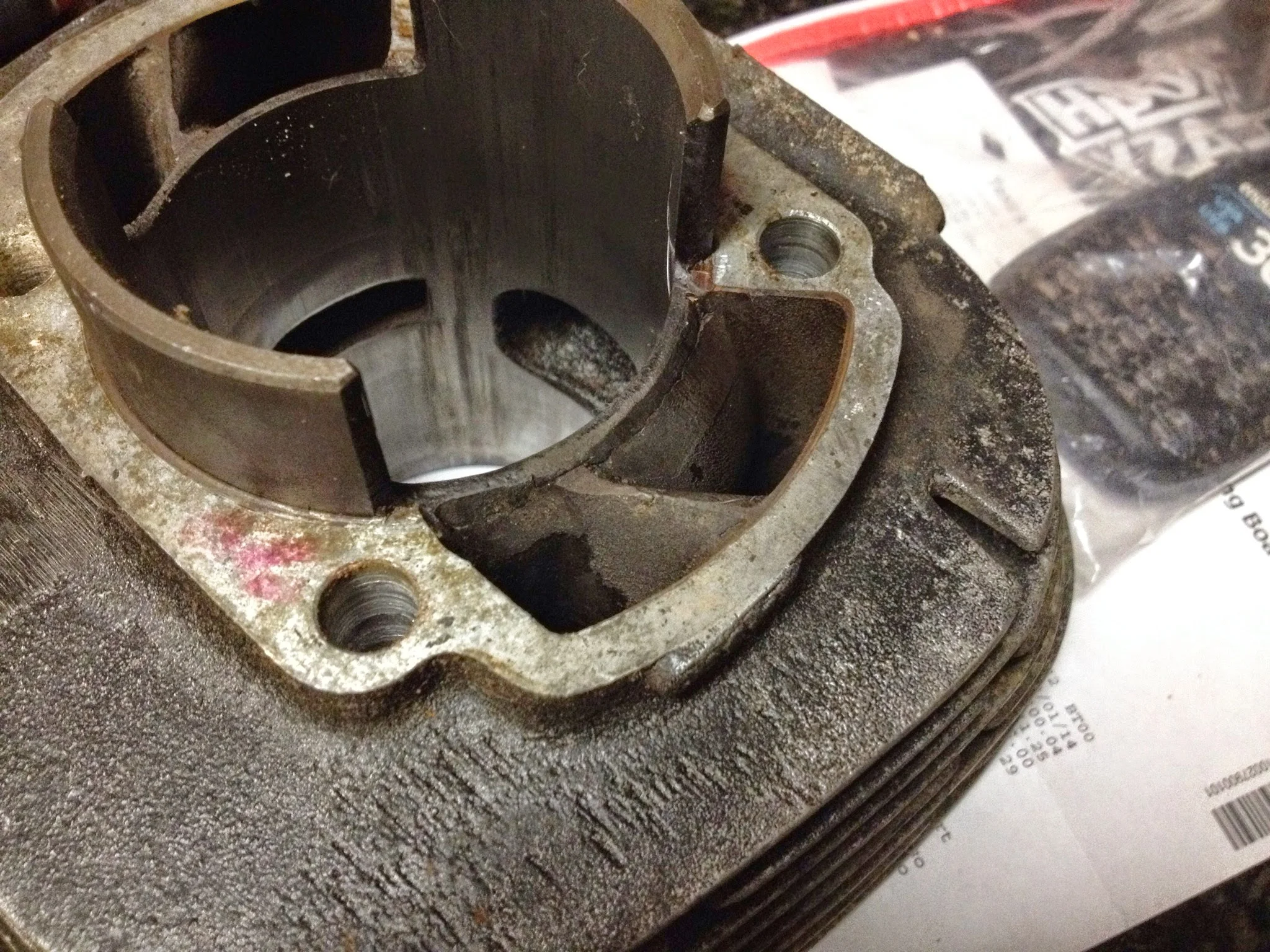
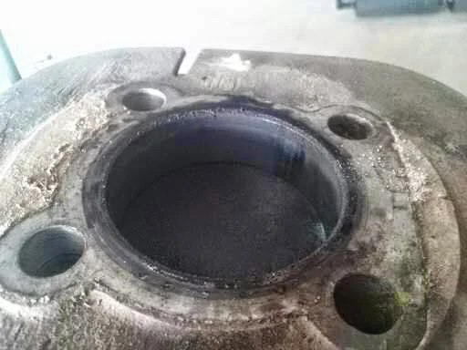
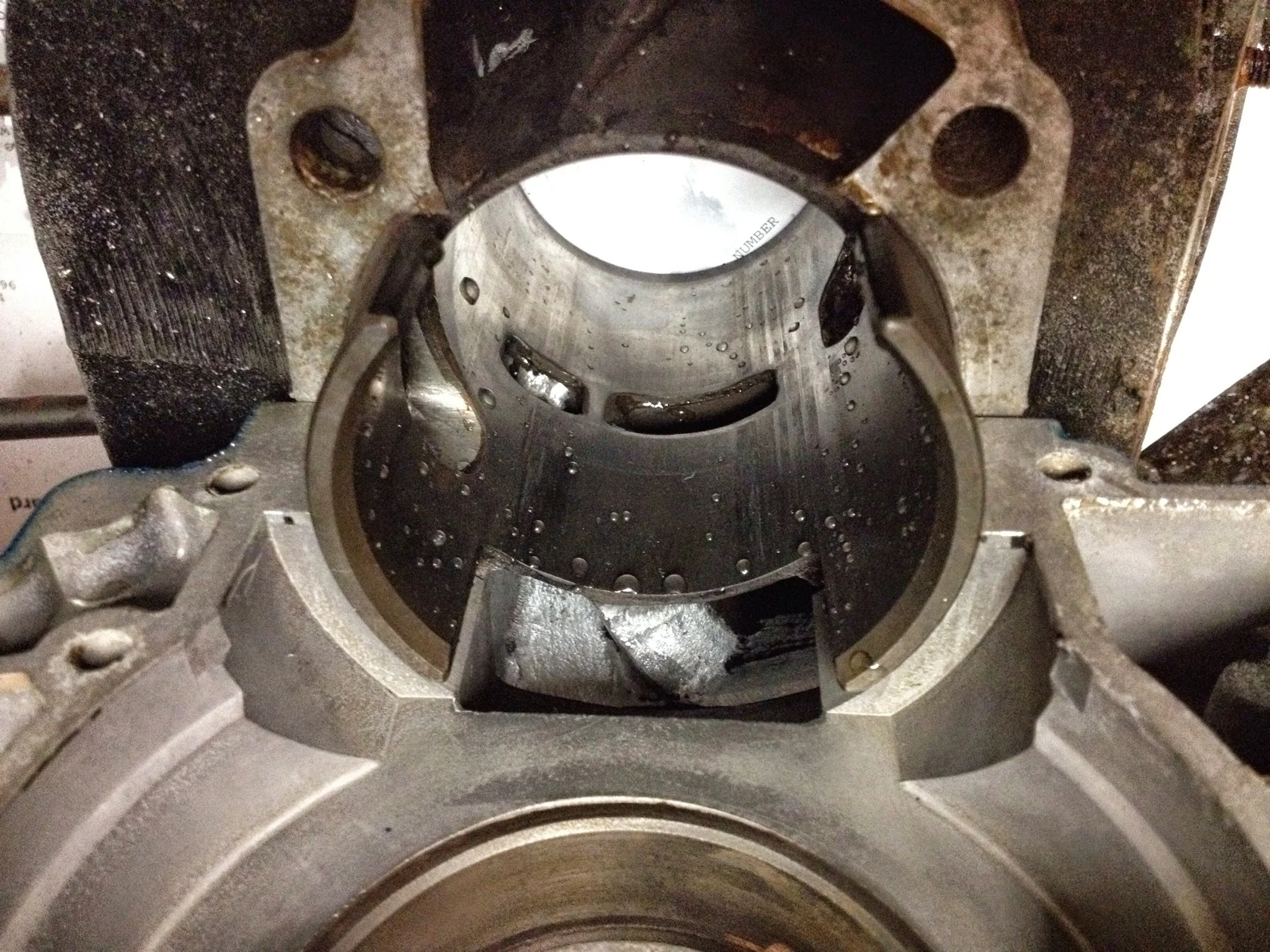
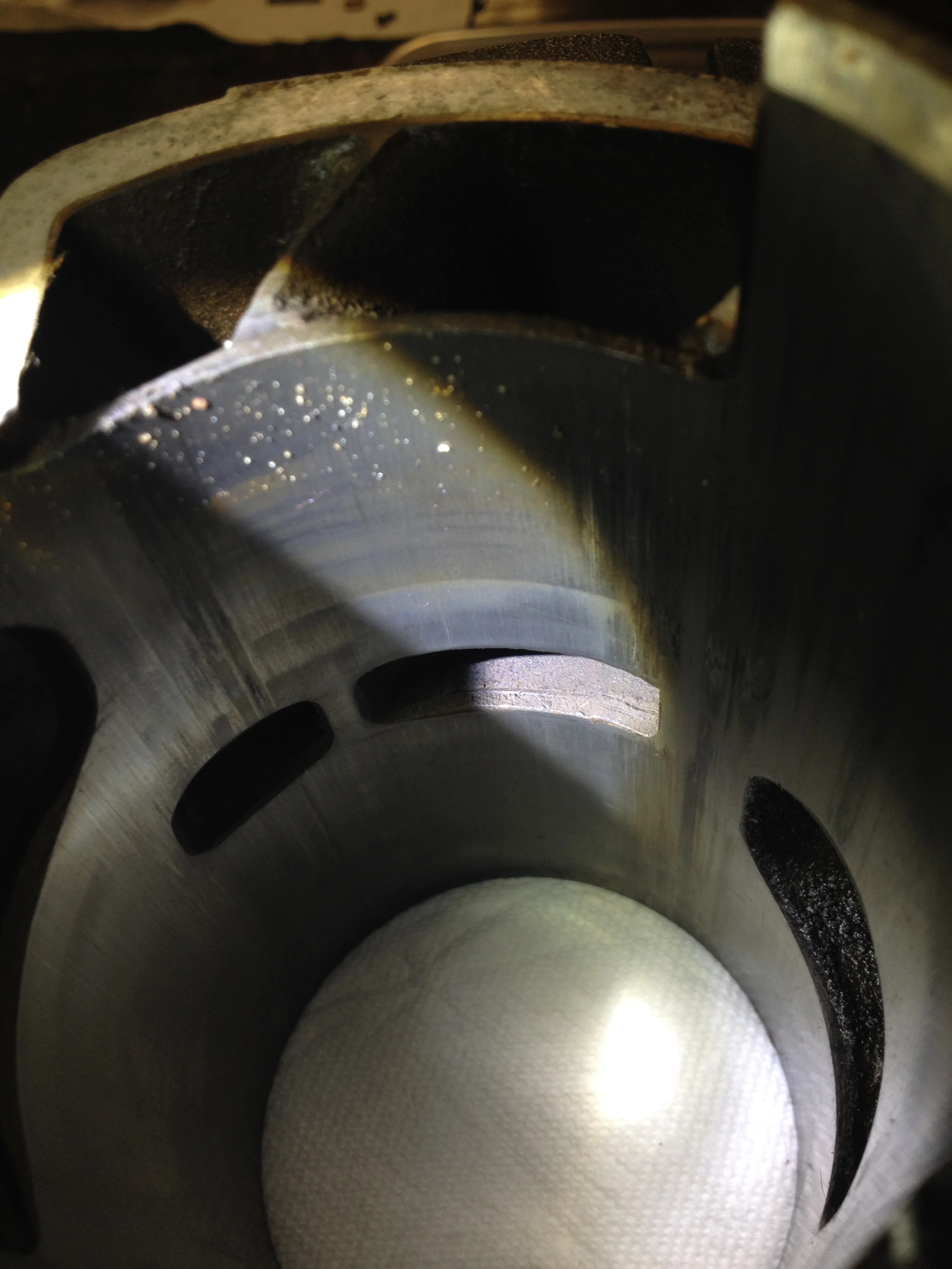
Some grinding done to the xfer ports before I got there
So I started with the transfer ports. Big chance to help smooth air flow, small(er) chance to really ruin things. When I got the cylinder, I could have sworn something had been done to the head. I had high hopes that it was a rare performance part from Yamaha, but having no way to substantiate that, I’m 98% sure it’s a factory, run of the mill cylinder. Most likely the 14 year old kid who had the bike before me, or the owner before that, did some work to the transfer ports. It's cool to think that some old guy back in the 70s did this to hop up his bike. You can see the color difference between the regular cast material and the material that was ground down years ago. Given the fact that the inside of the engine was so clean and the bike in general looks like it was never used, (wheel bearings perfect, hubs still showing clean grease, transmission gears showing almost 0 wear) I think this is old work, not done by the kid I bought it from.
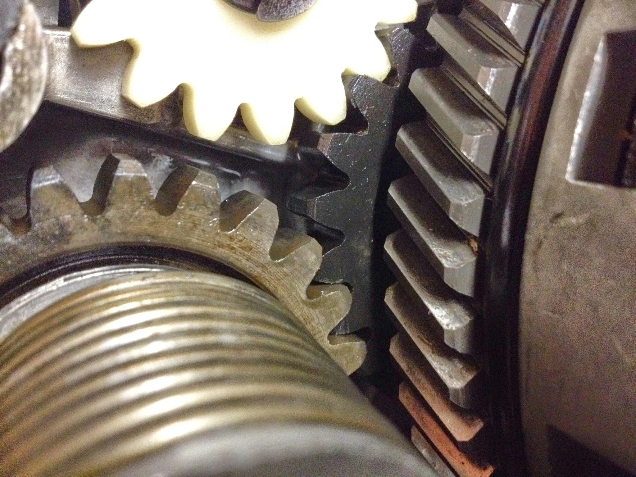
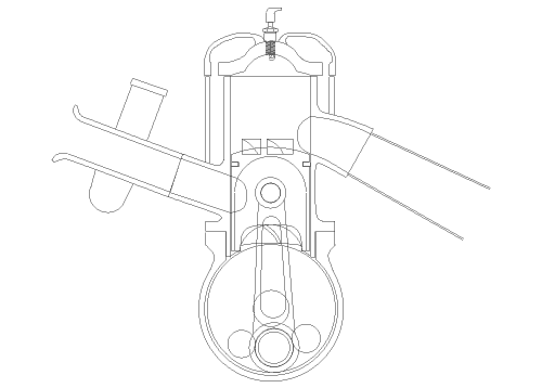
2 strokes don’t use valves and camshafts to control air/fuel and exhaust. They use “ports” which are really just holes in the cylinder that allow gasses to flow through at certain times.
The 2 stroke relies on the crankcase to hold the air/fuel/oil mixture, relies on the transfer ports to get this mixture in to the cylinder, and relies on the exhaust port to get the spent gasses out of the cylinder.
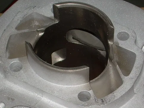
Stock transfer ports on a GYT Cylinder (stolen from Vallyrider and his rebuild thread, http://advrider.com/forums/showthread.php?t=557469
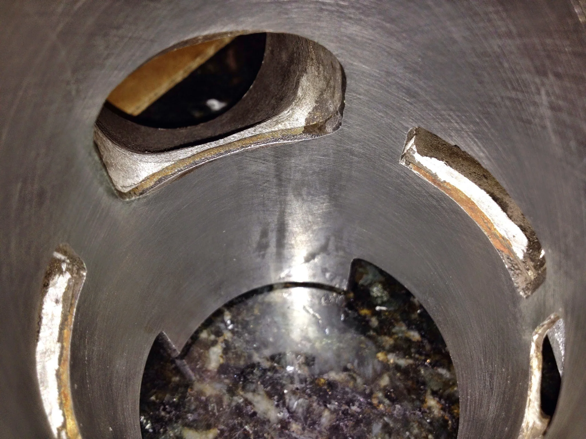
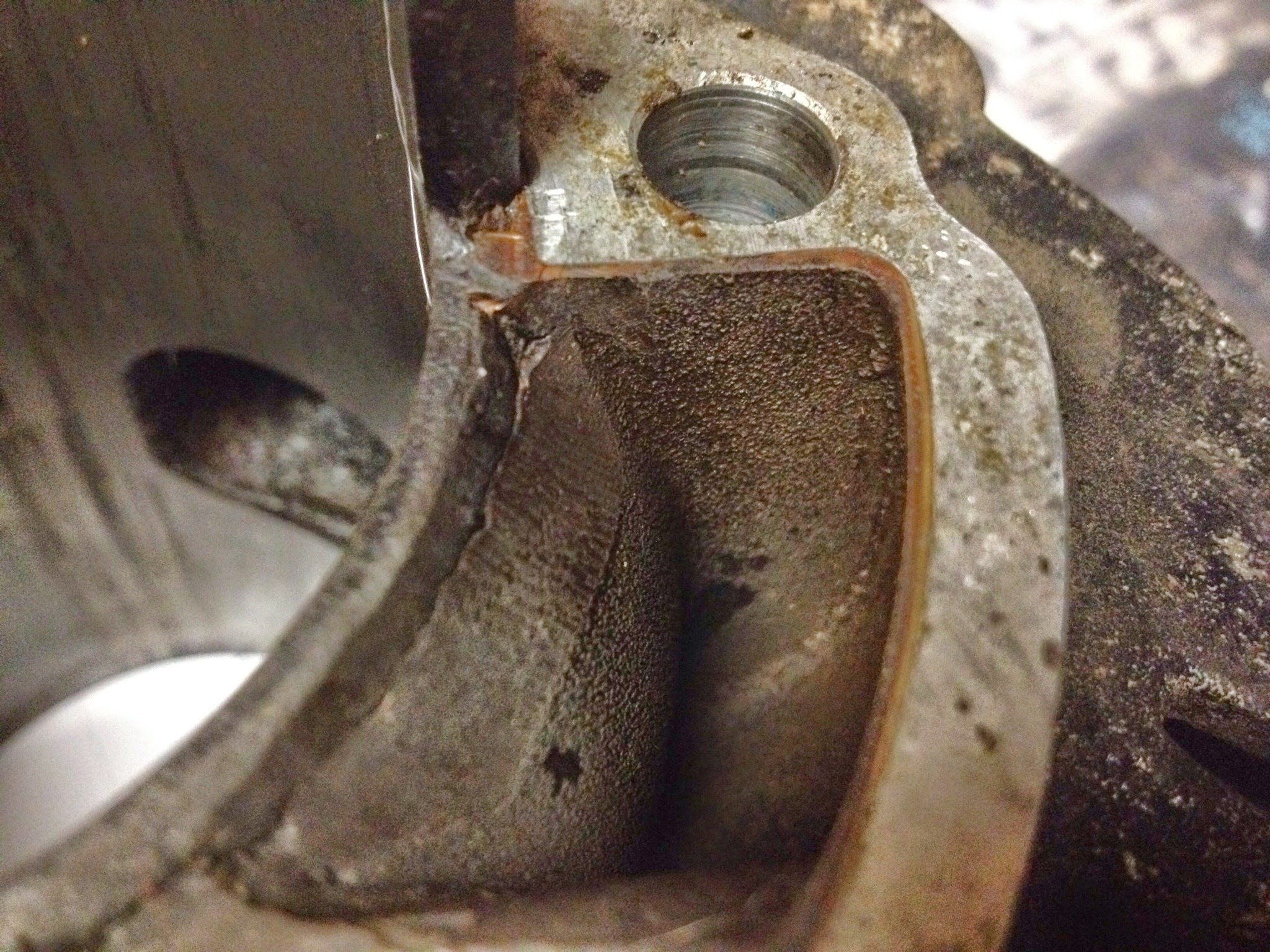
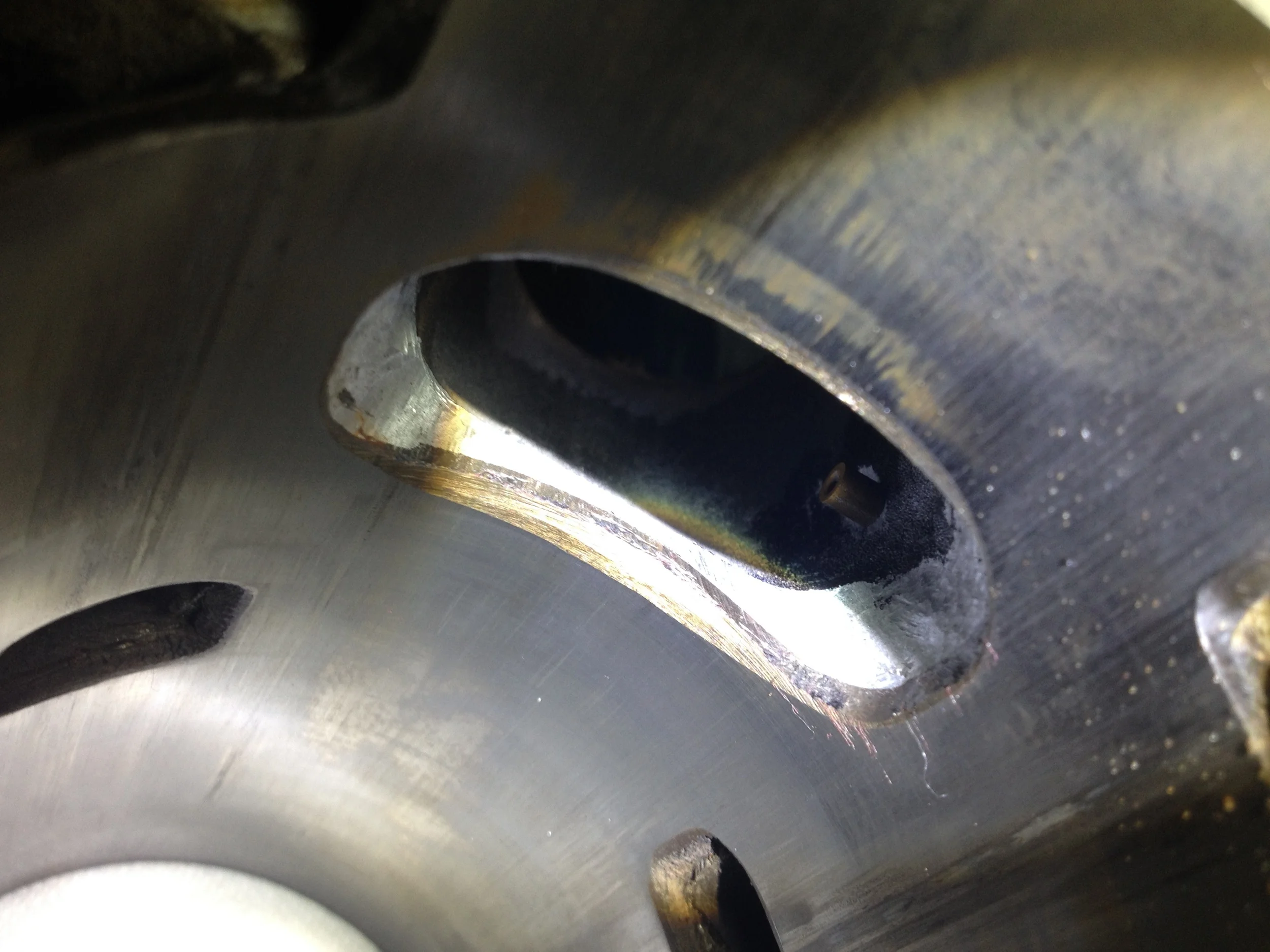
In the photo to the right you can see a thin dark "stained" area for lack of a better work on the flat cylinder surface. To contextualize, the cylinder is upside down in this pic. When installed on the motor, this surface is in contact with the crankcase. This dark stained area over hangs in to the crank case, disrupting and obstructing a portion of the flow. This part is easily ground away to port match the cylinder to the cases.

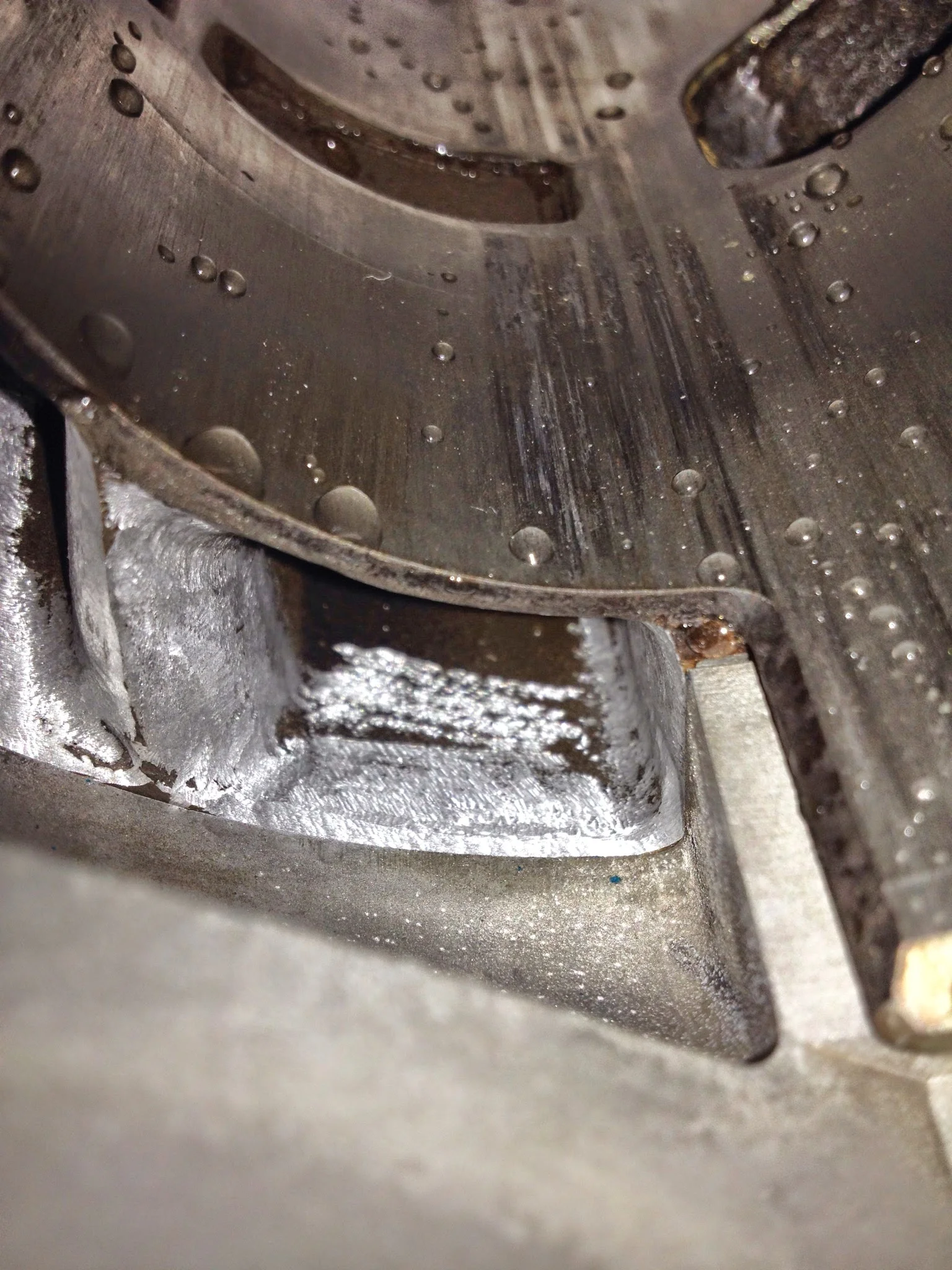
Why port/case matching helps. The person before me filed down the center divider to smooth air flow.
If you look closely in the center of the picture where the case (grey silver color) comes in contact with the port (the two black/brown open holes) you can see the difference in surfaces.
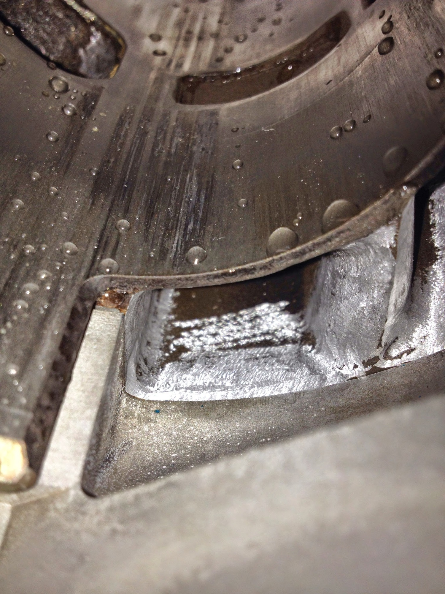
Close up of the surface and material removed with a carbide bit to match the transfer port to the case. This will be smoothed with sand paper and then be finished. You can also see the scoring in the cylinder wall, which is why it needs to be bored.
The engine manages to do all this with nothing but a piston, the changes the piston creates in air pressure, and it’s path of travel up and down the cylinder. Piston Port induction. The earliest, simplest, (most inefficient) form of 2 stroke awesomeness. There’s some good info online about how they work, but here’s a good animation from Hooniverse.com
So porting…why not make the port as big as possible, polish it mirror smooth, and profit?
That’s pretty much the plan on 4 stroke engines (pretty much everything today) with the caveat being that if you port too much, the port walls are too thin. Behind the port walls of almost every 4 stroke engine- water jackets that transport coolant. If the ported wall is too thin you can get a leak, and that’s all sorts of bad news.
For 2 strokes…since the efficiency of the engine relies solely on the volume of air the piston is able to move in 1 stroke, if you make the ports too large, the gasses will not move with adequate velocity. The whole deal with two stroke porting is balancing velocity and volume. The other mess that comes in to play is port “timing,” or when ports open in relation to one another and for how many degrees of the rotation of the crankshaft. There are some good DT1 port maps out there based on the DT1MX, which came with a higher performance cylinder. Doing that level of porting requires a lot of time, skill, and faith. All of which I have…but I have it in baby steps.
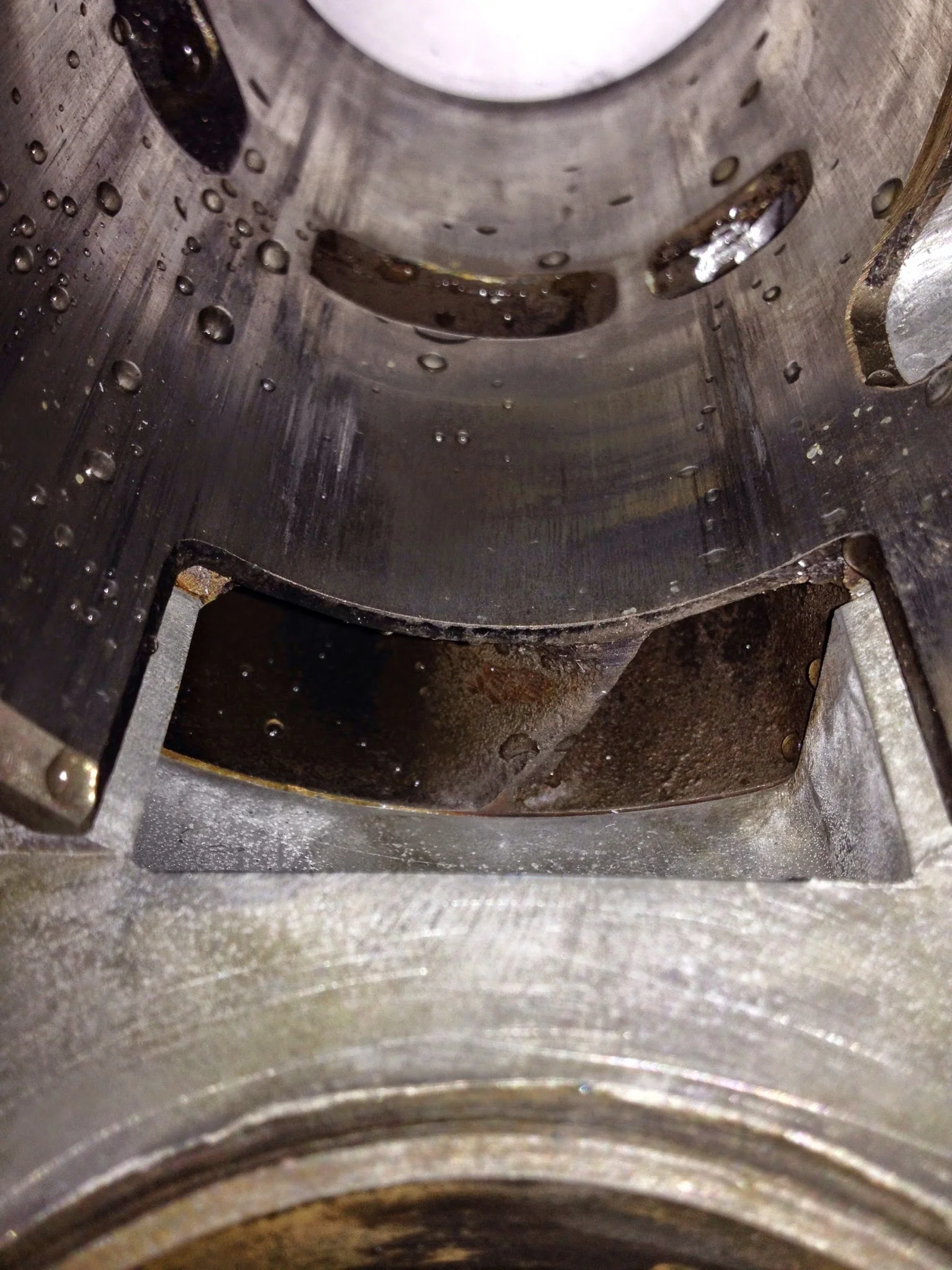
How it looked when it was first opened...
I was going to buy a new cylinder for this engine anyway. The kid before me ran this thing without oil (he tried…he spliced the oil line in 3 places with 3 different kinds of tubing, and he did put 10w30 in the oil tank (not the right oil, kid…)) and the piston did some damage to the cylinder wall. I broke out the dremel to begin smoothing out the transfer ports from the work that was done before. I feel like I did well. I need to do hand sanding, but I didn’t take much off and smoothed transitions where possible.
After looking at prices of cylinders on ebay (and their terrible condition) I decided to seek out a machine shop around Houston that can do the work. Harold’s machine came up as the place from a couple of recommendations, and as of today that is where the cylinder sits.
I’ll need to get a piston before he can finish the work, so there is that. But once done, I can finish the ports by hand, powder coat, and put it all together.
It has dawned on me that I have nowhere to start this thing around here, living in a small apartment. It may have to be transported to San Antonio in pieces and assembled there.


Motorhead
lot of small things going on and moving forward here.
It started a couple of weeks ago when I decided to drop in the bearings. They had been sitting in the freezer for a long while and something motivated me to finally start putting the engine back together.
Frost on the inner race
In the oven the cases went. Somewhere around 300 degrees for a few minutes. After the cases were hot, they were taken out and the frozen bearings dropped right in to their races. There was one exception, a needle roller bearing on the small end of the transmission. It took some mechanical persuasion. All of the others literally dropped right in. As the freezing metal quickly warmed in its hot new home, the bearings expanded to their tolerance and stayed in place.
Before being sent off.
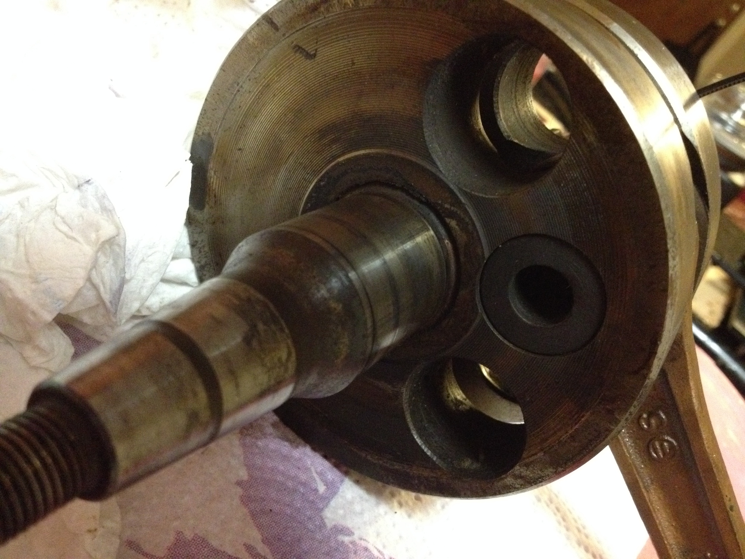
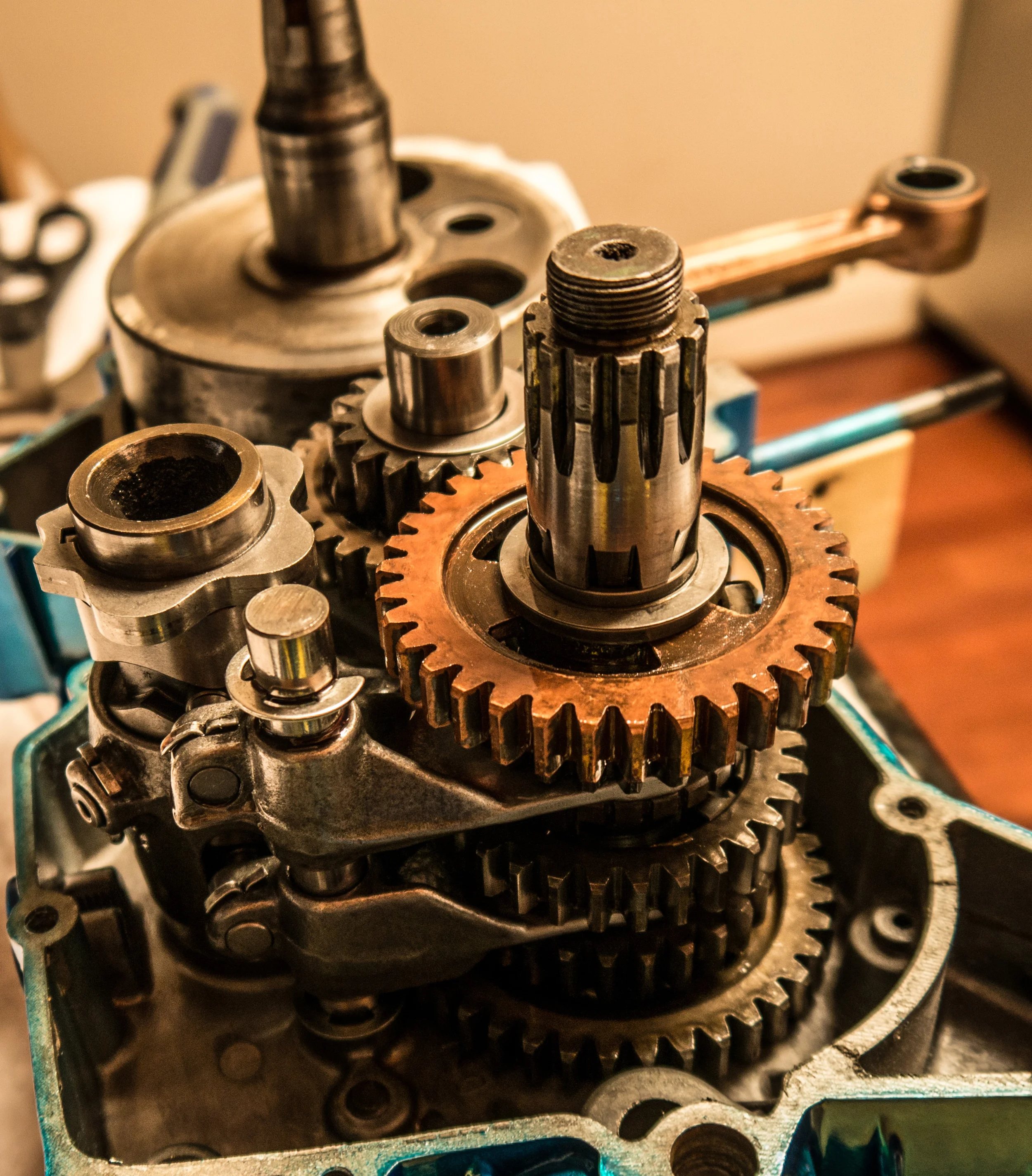
The rebuilt crank came next. I stared with the shim side (gear side, clutch side, right side, whatever…) and pressed it in to the case as best I could using a plastic mallet.
The transmission came out of its foil packet (where I’d placed it some 7 months earlier) and I dropped it in to its place. With a little tweaking and coordination, I was able to get both gear shafts and the shift forks all lined up and in place. This isn’t particularly hard, but it takes some synchronous movement of parts.
Back in college I remember taking apart an old GT80 for the hell of it. When it came to opening the cases…I was blown away. So much stuff. So many parts, so many washers, shims, forks, bearings…I gave up, sold the project.
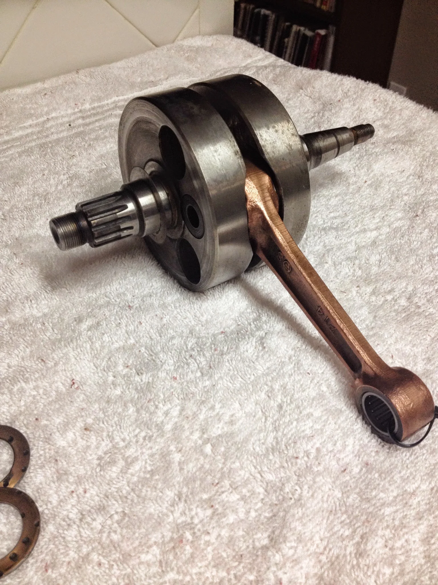
Rebuilt. New thrust washers and lower bearing (and upper bearing)
After doing 2 of these, they really aren’t that complex or scary. Intimidating they may be..but parts diagrams are helpful and every part is engineered with a purpose. There’s a 2 part retainer and a shim that goes on the transmission. Without those 3 little metal parts, the whole trans can be disassembled down to gears, clips, spacers, and shafts. These tiny parts hold the bronze gear in place.
By far the best advice I ever read was to just put the whole thing in foil, though. It keeps the small parts from falling off and walking away. It preserves everything from accidental bumps, moves, falls. And there is not really anything on the transmission to be serviced (unless you have to rebuild/replace it like I did on the DT2) so it’s easy to set it aside.
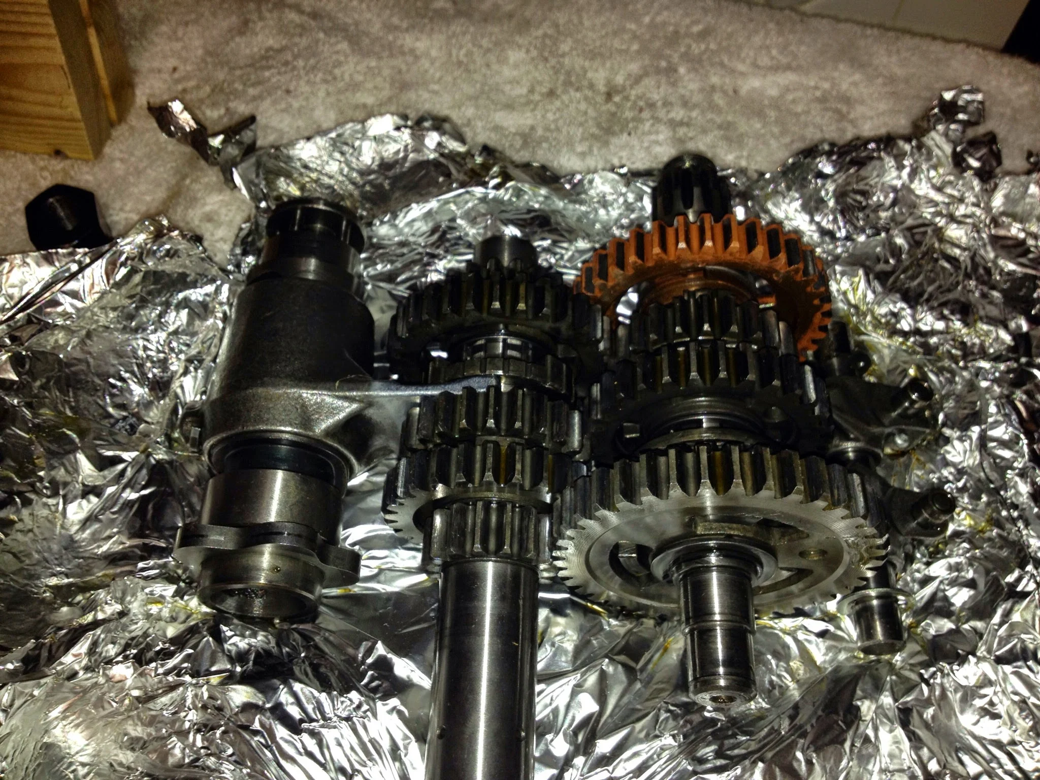
unwrapped
Crank is in, trans is in…next step is bonding the two cases with a sealant/adhesive. In japan, they used Yamabond 4 or 6 or some number. The numbers are different formulas. I’ve used a product called motoseal that smells like plastic model adhesive (a wonderful smell) and works well. It’s a semi-drying viscous grey matter that is very very sticky. After running a bead on the sealing surfaces of the two cases, it was time to squeeze them back together.
I’ve taken apart and reassembled motorcycle engines many times in the past without the right tools, and it always leads to serious damage. One of the better investments I’ve made- A case splitter and a crank puller. The crank puller screws on to the magneto side of the crank and pulls the crankshaft on to the case. This process was somewhat hard on the DT2. I’d tighten the tool and pull the crank on and then tap the rear of the case to make sure the transmission drive shaft was coming through the case as well. The DT1 went together with ease. New allen cap screws were used to cinch everything together, the crank was tested for mobility and its centered-ness, and that was that.
There really isn’t a lot inside of the cases.
Internals
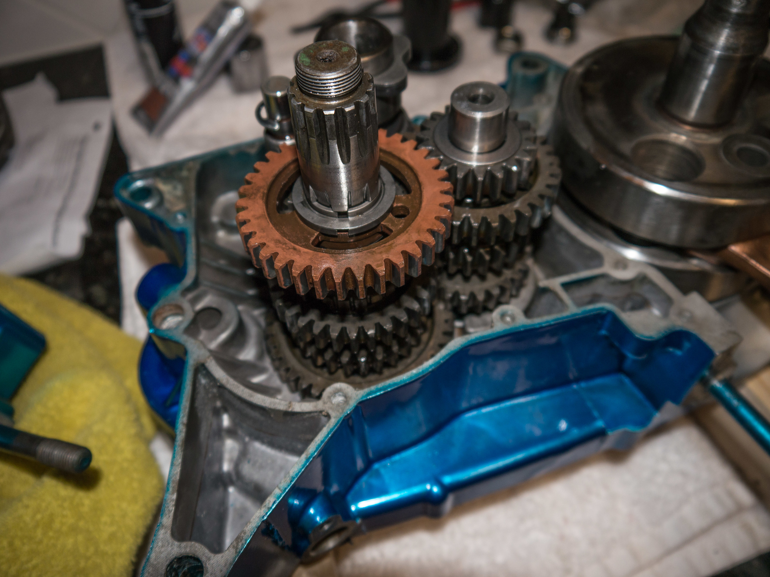
With the cases together, the other items can go back on. Stator and flywheel went on with no trouble. With the exception of the countershaft sprocket, there’s nothing else on that side of the engine.
The other side is where all the fun is. Clutch discs, plates, gears, shift mechanisms.
When I took everything apart, I zip tied it together. I know that probably doesn’t make sense, so here’s and example-
The gear that goes on the crankshaft has a rubber o ring, the gear, a washer, and then the nut. My biggest problem when putting these things back together is remembering the order of things.
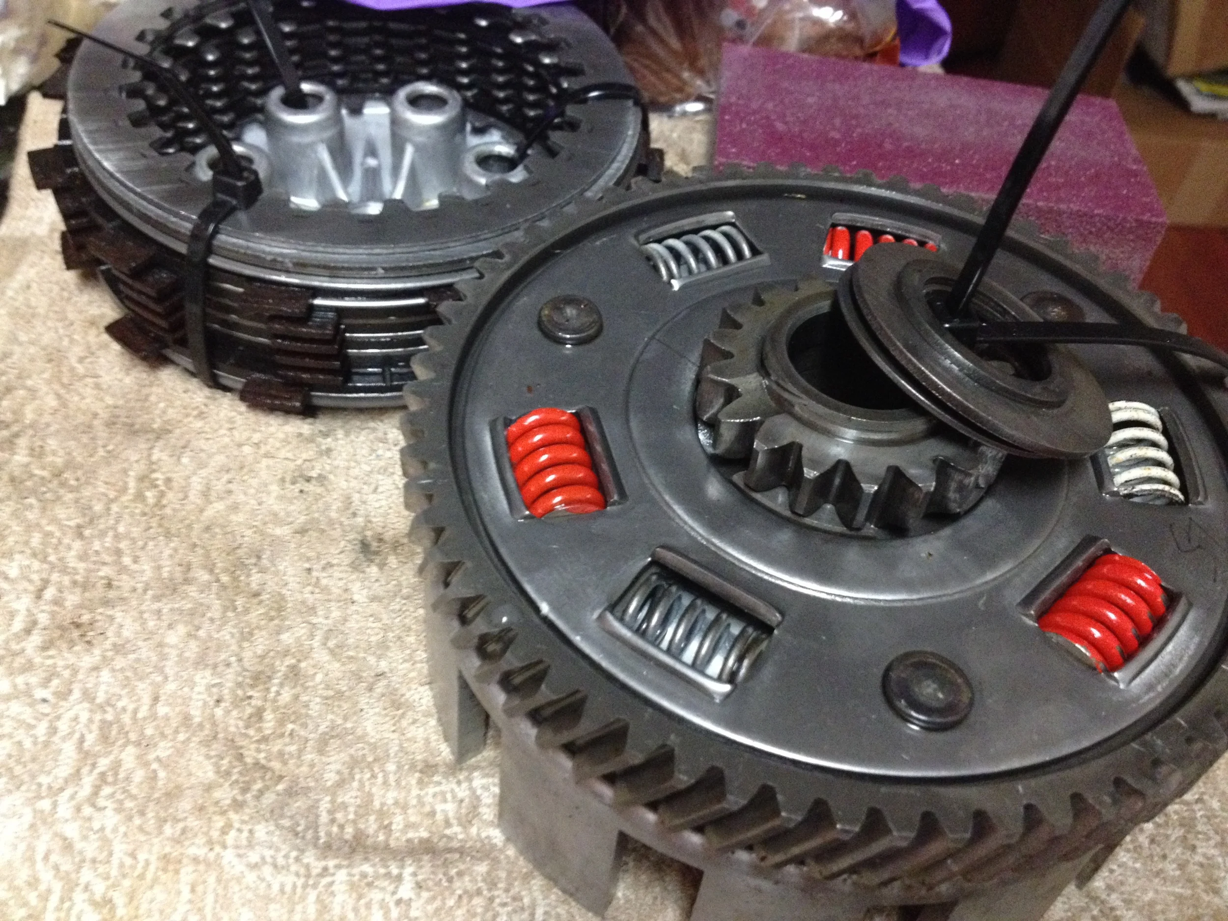
Clutch discs in background ziptied, clutch baskets/bearings in front
The clutch basket- there’s a spacer, a washer, a bearing, a washer, a race that goes through all of those, an outer basket, inner basket, and then the clutch discs/plates.
When anything of multiple parts came off (and everything has spacers, washers, circlips, etc) I zip tied them together in the order they came off.
This made things 1000% easier when it came time to put it back together 7 months later.
All of the small parts went in zip lock bags and grouped by function. All the clutch hardware went together, all the shift hardware, etc. I had a scare when I saw a small part in a bag and had no idea what it did. I shortly found out that it went on the shift mechanism though, and that tragedy was averted.
So the crank gear and all that goes with it went on first, then the clutch bearing sequence (most complicated part of the engine, I think.) but not the clutch baskets.
You can’t get to the shift mechanism when the baskets are in place. So I hooked up the shift shaft , detent arms, and shift drum. Tachometer idler gear and its washers/clips goes on, clutch baskets go on, clutches and plates go in, clutch activation system goes in (a ball bearing, a rod, and a little cap) and that gets bolted together.
The nylon tachometer drive gear had a catch in it when I was testing it to see how it spun. I decided to take it off and see why…and the drive gear is trashed. I’m pretty sure I did it because I don’t remember seeing it that way when I took it off, but I honestly never looked.
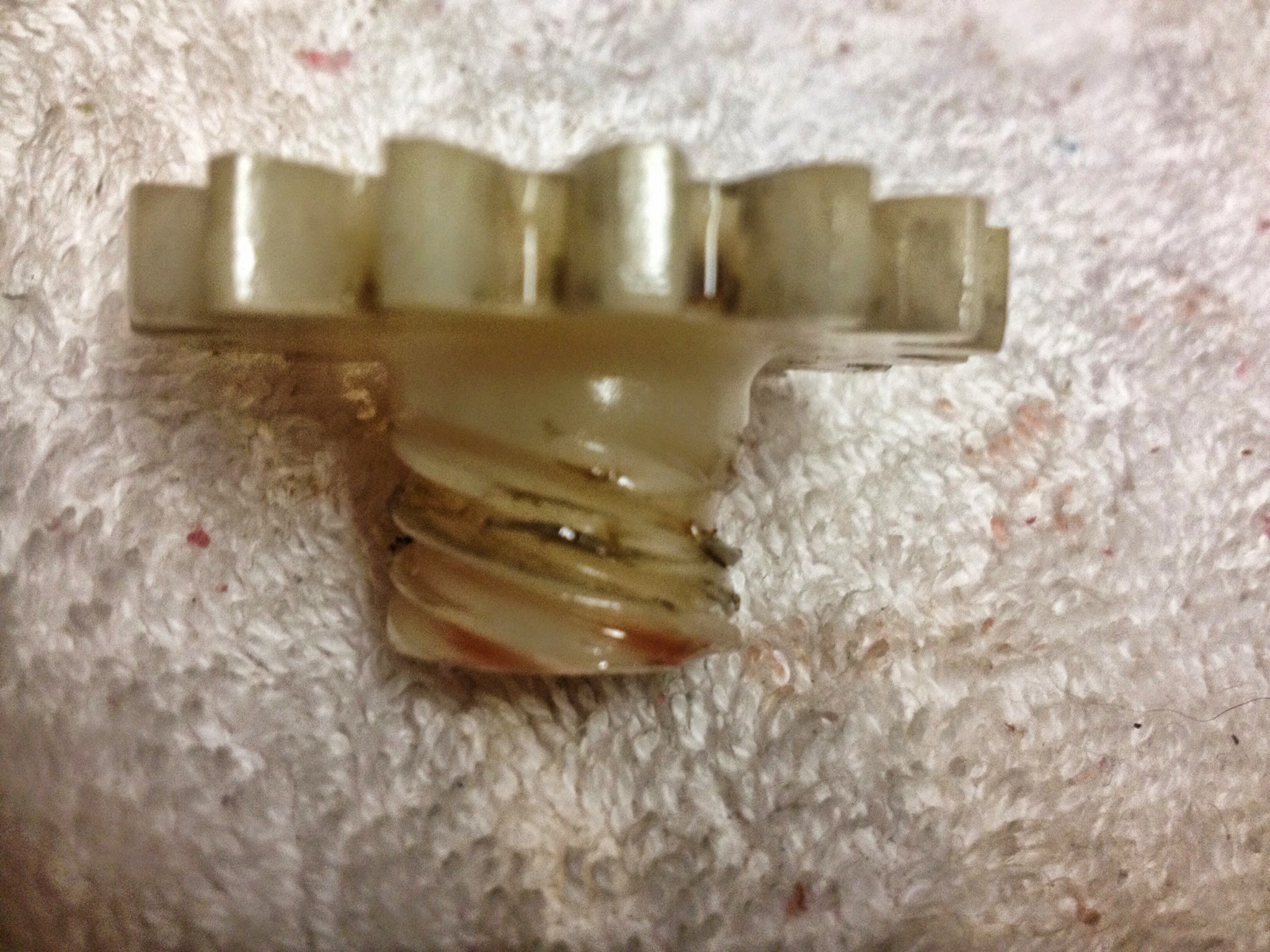
Stripped worm gear
So- I need one of those from eBay. Oil drain and shift drum detent gasket are ordered along with a washer for the shift shaft and a circlip for the oil pump drive shaft.
Other small things like oil pump seals, swing arm bushings, swing arm nut, and some other things are in the mail.
Big needs right now- Tach drive gear, shift shaft washer, oil pump circlip. Once I get those, I can put the bottom end entirely together.
Big needs in the future- Cylinder head bore, piston/rings/pin, fuel petcock, fuel tank.
That’ll make it run.
Not too far away, but I’m starting to realize that these projects are never as efficient as I think they will be. I may need a cheaper hobby. And no one in hell is going to buy a bike with a blue engine.
One day I’ll learn.
For now…more waiting on the mail man.
Birth of Motoworks
I’d been waiting for a few reasons. I’d gotten a good routine and method down for powder coating. I felt good about the procedure, even with all my limitations (tiny apartment, small patio. 1 gallon air compressor, small oven that I also cook my food in)The weather forecast was good. Sunny, low humidity. And I had nothing else to do.
I started by testing out my powder coating stand that I’d build last night. Without a doubt, the hardest part about doing the wheel was the fact that I didn’t have anywhere to set the oven rack outside of the oven. These things I am coating are hung from the wire rack with wire…so setting it down isn’t an option. I built a stand out of some 1x2s. Made my life 1000x easier.
I put the flat black powder jug on the gun and got around to coating some parts I’d been meaning to for a long time. Brake lever, kick starter, shifter, brake rod, and the new tw200 triple trees. I also decided to powder coat the carburetor. The dt2 came with a black carburetor and I’d never seen such a thing. I liked it. I liked it so much that I set it in a can of b-12 chemdip and left the state for a month. When I came back…the carburetor wasn’t in a solid state anymore. So shout out to B-12 Chemdip for being some serious stuff.

Top cap on the carb cooked too long
Carb was the most intensive pre-coating work. So many hole and passages to plug. Floats have to come out, choke lever, gaskets, o-rings. It’s a pain to tape it off but I got there after a while.
I also set aside all the small parts that I wanted blue. Fork bolts, carb bowl screws, brake return spring, etc. I had a nice operation going in the morning. By early afternoon I had some results to be proud of.
Big mistake #1- I wanted the throttle slide cover that threads on to the top of the carb to be blue. All was going well. It was baking with all the other blue parts, but due to its thinness, it cooked faster than all the other parts and I didn’t take not. The finish got bubbly and nasty. One day I’ll strip it and recoat it. It will be hard to see when it’s on the bike, and I didn’t have the heart to re-do it then.
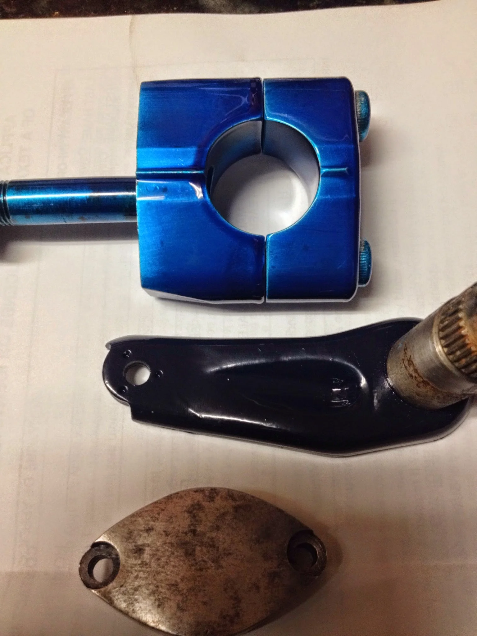
TW200 trees before
Really like how the triple trees came out. They look awesome with the blue bolts. Did some measuring and found out the lower race on the triple tree is a 30mm Inside Diameter…that means I have to order a different $25 bearing. But at least it’s out there, and it’s not one that’s impossible to find.
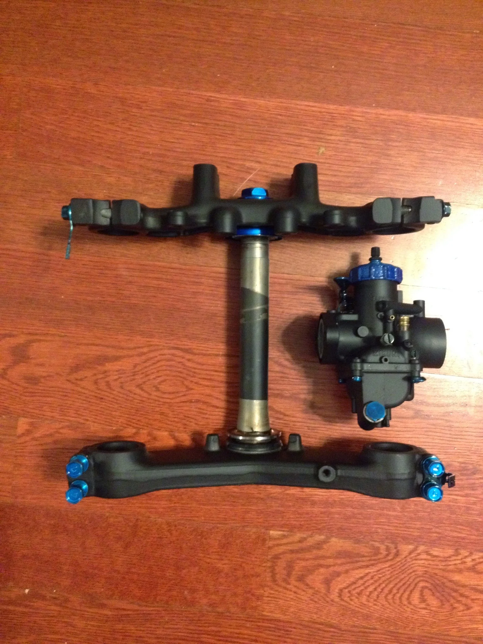
Black and blue
Also scored a deal on eBay for some 1990 YZ80 forks. The Yamaha YZ series is the offroad/motocross style bike. Back in 1990, and on this tiny bike…the fork legs were 33mm. So they’ll bolt in to my triple trees, and they are designed for a disc brake. I really want a disc brake for no real reason.
Bad news is that I’ll need to lace the YZ80 hub (which I’ll have to buy) to a TW200 front rim (which I’ll have to buy) and I’m not even 100% sure that will work. Might have been a better idea to just get an old school YZ80 front end and bolt that on. I may end up not being able to make this work, and so I’ll have to go with tw200 forks if that’s the case. I really want the fat 18x2.50 rim up front, and the same in the back. Developing situation.
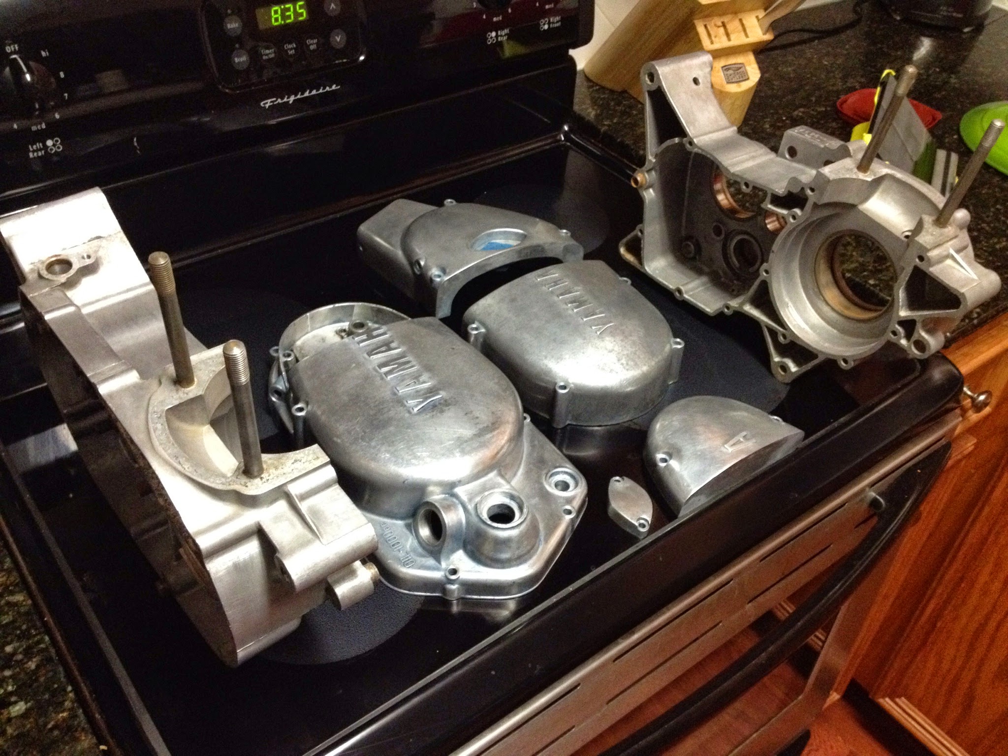
engine bits. Uncoated.
After the flat black coating, I decided I may as well get started on the engine cases. In to the oven they went for preheating. The process for all of these engine parts is this-
Wipe with acetone to remove oil/grease/fingerprints (didn’t do this on the wheel hub, which is why it bubbled)
heat in oven @395 for 10-20 min
Remove and let cool a bit on the powder coating rack outside
wipe with acetone to remove residual oil
Hook up air to powder gun, ground the parts, start shooting powder.
Open door with foot, remove rack from stand, transport to oven
watch for the powder to flow/look like it’s wet
Set timer for 20 minutes.
remove parts when done, set on rack outside. Allow to cool slightly.
Refill air compressor tank
Change out powder colors
Coat parts while they are hot, but not too hot.
Open door with foot, remove rack from the stand, transport to oven
watch for the powder to flow.
set timer.
Remove parts when done, allow to cool all the way.
Sticking on a buffalo that was hand cut with a Feather brand razor blade. (the kind made to shave hairs, not a utility blade)
I had enough parts to warrant doing this process 3 times. The first rack was the engine cases. The 2nd rack was the side covers, and the 3rd rack was the whole engine loosely assembled.
I powdercoated from 9am to 9pm today. But I really like the result. It’s almost exactly what I imagined.
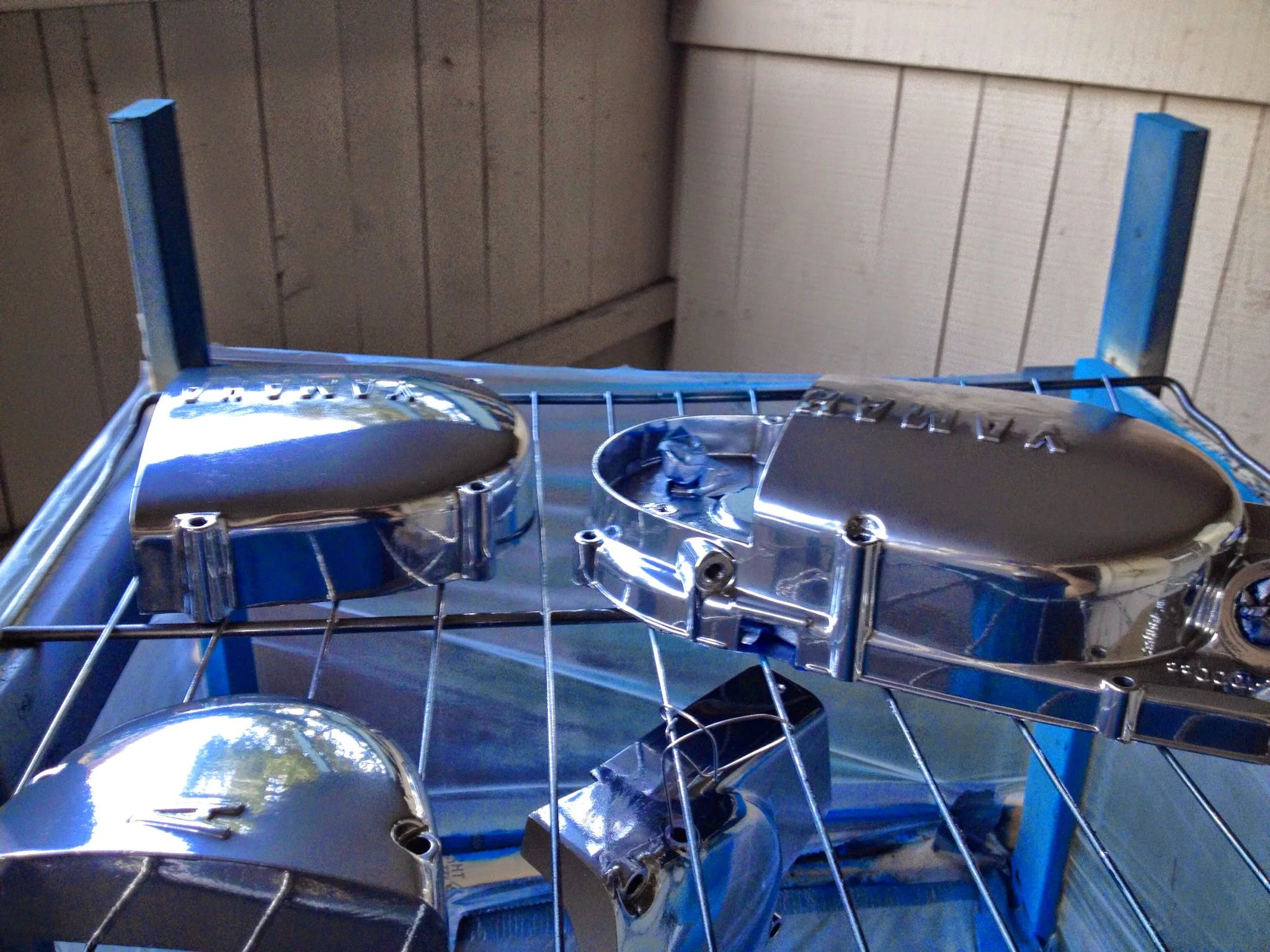
2nd big mistake came when laying down the chrome base on the engine covers. I’m using a 1 gallon pancake compressor…not ideal. 2 times it delivered powder in a huge avalanche. I didn’t want to wipe it off and redo the entire thing all over again so I let it ride. After baking, it smoothed out a bit. They look like odd bulbous mounds. Again, not very noticeable, but not perfect.
Chrome
Having worked out minor details and kinks on the engine cases (which was the plan, since the cases aren’t as noticeable as the covers) I started on the side covers around 5pm and was aiming for perfection. I taped everything off that needed to be and began with the chrome base layer.
It was the sweetest looking thing I’ve ever seen. Looked very good except on the oil cover side. I don’t think I got enough powder on it, but I could live with that.
Letting the chrome layer cool is a tricky proposition. The blue will not adhere to a chrome-coated part. I’m thinking this is because of some metallic properties of the chrome powder. The top coat will only stick when the chromed part is hot enough to promote adhesion. Powder the top coat when the chrome is too hot- it’ll clump and glue itself together. Let the chrome cool too much- the blue won’t stick at all no matter what.
Before the last layer of blue
I let the chrome cool too long. I started laying down blue powder and it wasn’t sticking to all of the parts. So I did my best to coat them ones that let me, and then I put the whole thing back in the oven to heat it back up. Right when the powder started to flow, I popped it back outside and finished laying down the blue.
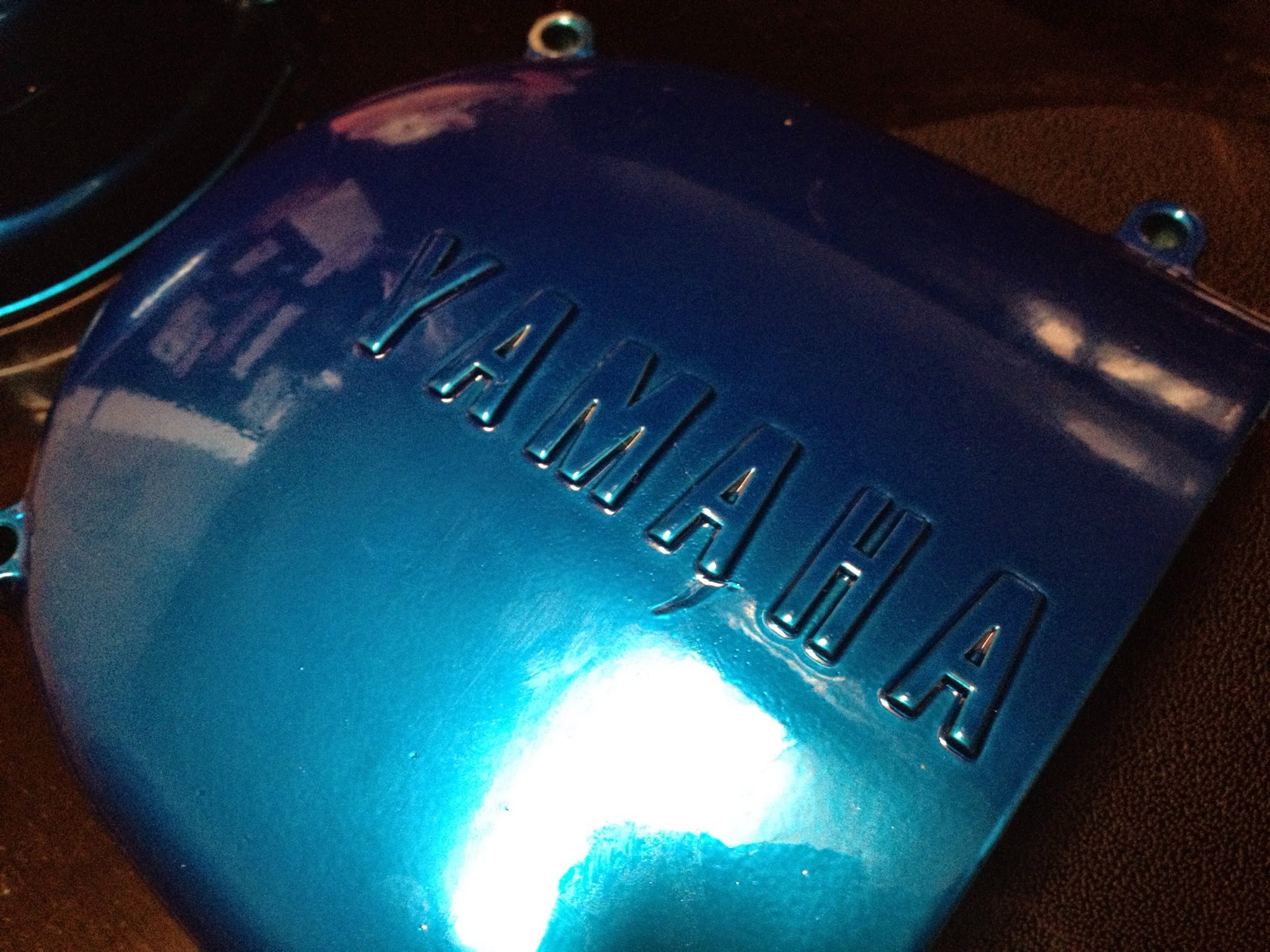
After it all cooled, I put the side covers on the engine, heated the whole thing up, took it outside, sprayed a last layer of blue on it, and baked it.
That took me to the end of the day. And I’m really happy with it.
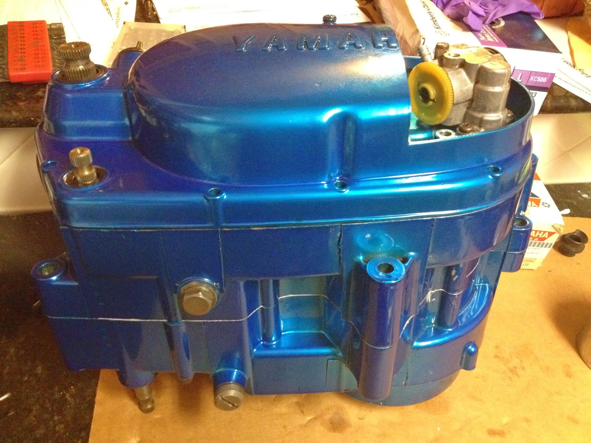
Cylinder will be matte black. The head will be black with one blue fin (that’s the plan for now…not sure how I’ll make it happen)
The engine is ready to be built as soon as I get my crankshaft back. It’s in Minnesota right now getting inspected and trued by Bill Bune (http://www.billbune.com/) If all goes well, I’ll have it back in a week. Bearings can go in the engine, and the bottom end will be back together in short order.
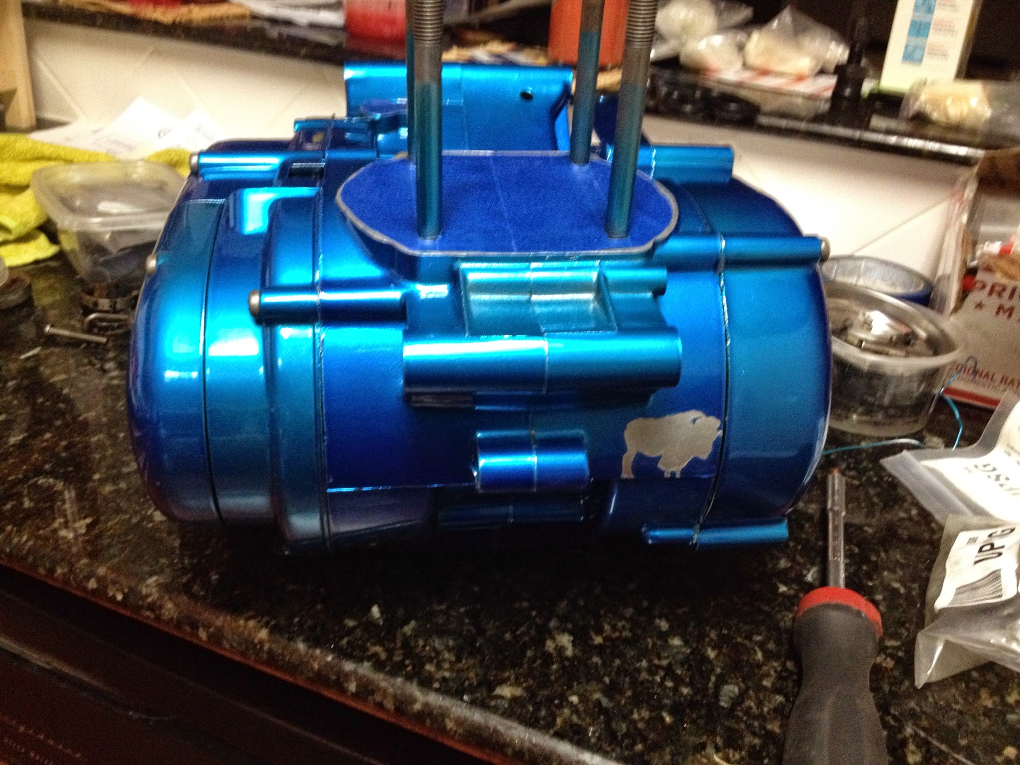
Bison on the right, behind the frame
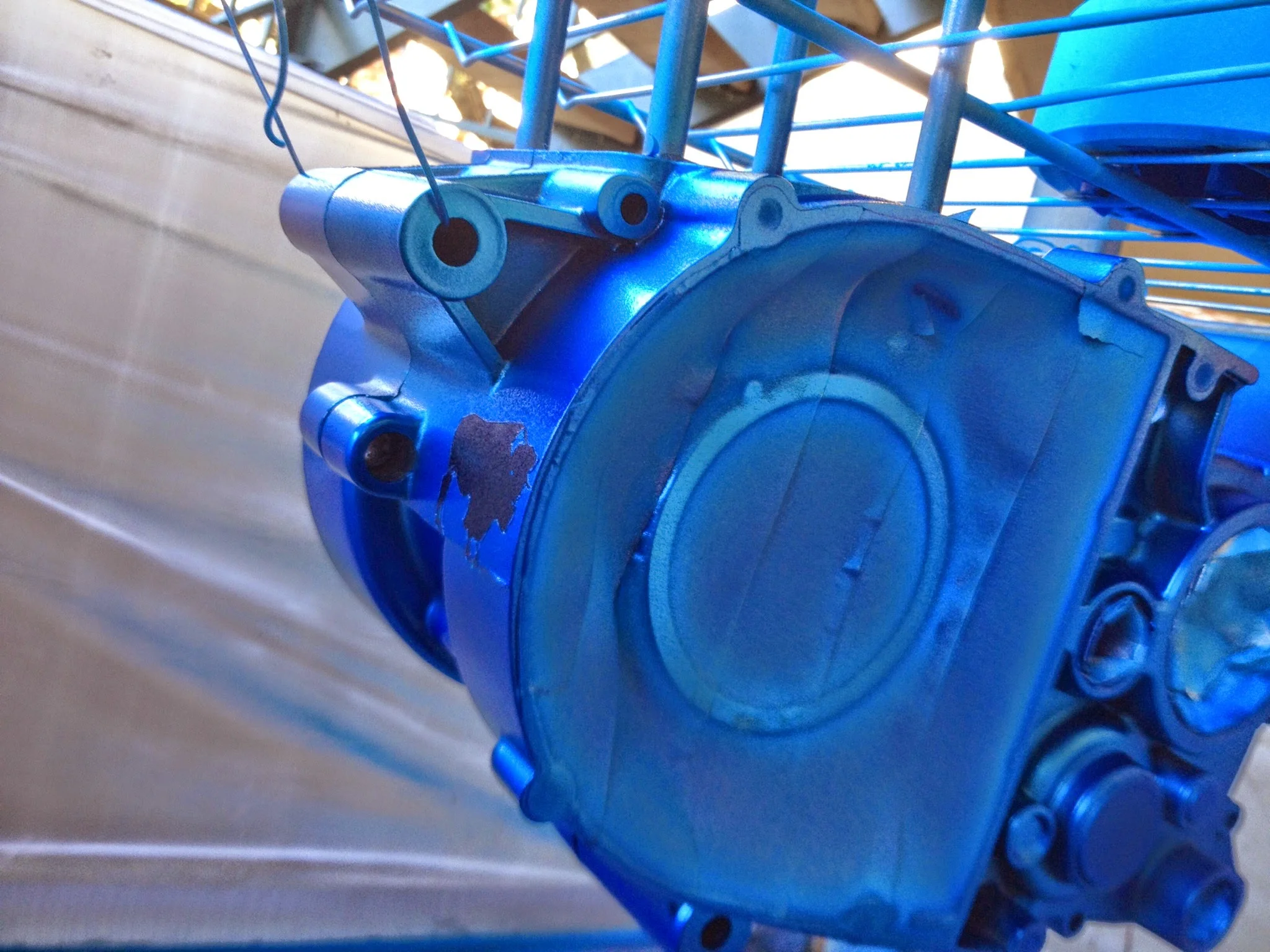
Bonus notes…I powdercoated the flywheel blue for the hell of it. There’s a ghosted buffalo (same one on the homepage of this site) on the magneto side case. It’s going to be covered by the skid plate but it matters that it’s there. It’s all about details…
I lost the engine bolts. Have no idea where they are….really hope I didn’t leave them in friends garage, because they sold that place….
Once the crank comes in, engine building will start. New gaskets, seals, yamabond, and clean internals await their home.
Rollin
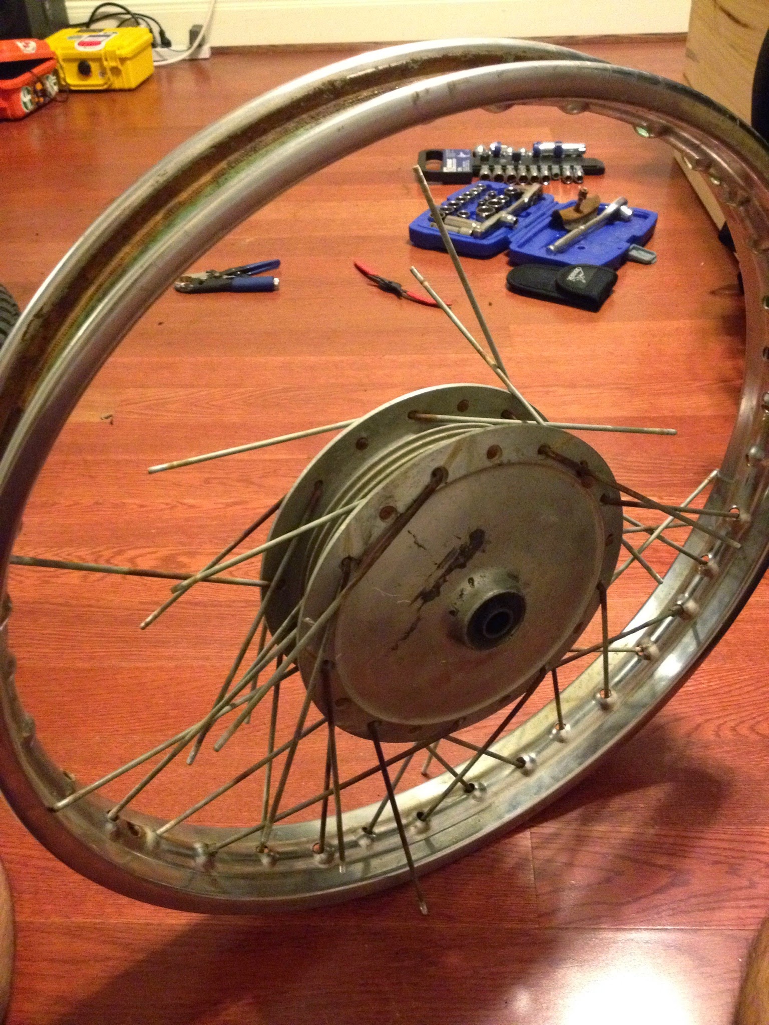
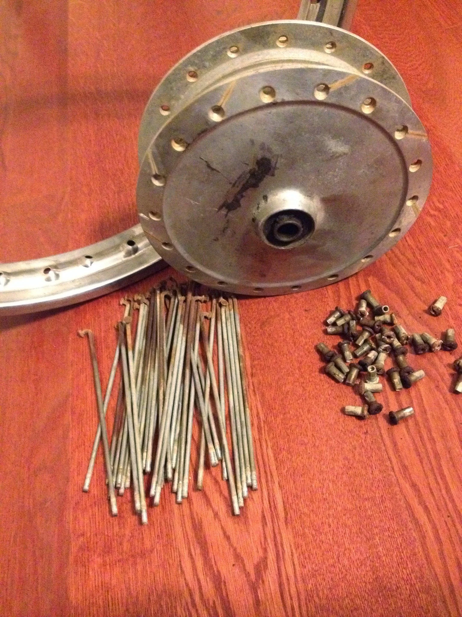
The past couple of days have brought gray skies and rain. Friday I spent the day taking apart the DT1 front wheel and testing the powder coating colors, methods, processes on it.
Powder coating- what is it? It’s a way to add a colorful, durable coating to something. It’s painting…except it’s dry. No liquids involved.
An positively charged powder is propelled by compressed air and shot out of a gun. The part or item to be coated is hooked up to a grounding cable. + powder attaches itself to the – part (polarity might be backwards, but principle is the same) So at that point, You have a part covered with a very fine dust.
In order to get the color to stick, smooth itself out, and attain its final attributes, it needs to be baked or heated via some other means. Typically 400 degrees for 20 minutes is common.
As far as durability goes…powder coating blows paint out of the water. I like the coverage better as well, and the fact that if you mess up, it’s just powder. Wipe it off, do it again.
It’s not a hard process, but it’s time consuming and there needs to be a lot of attention to detail as far as masking things off, cooking times, multiple coats of powder. Anyway, that’s basically what it is.
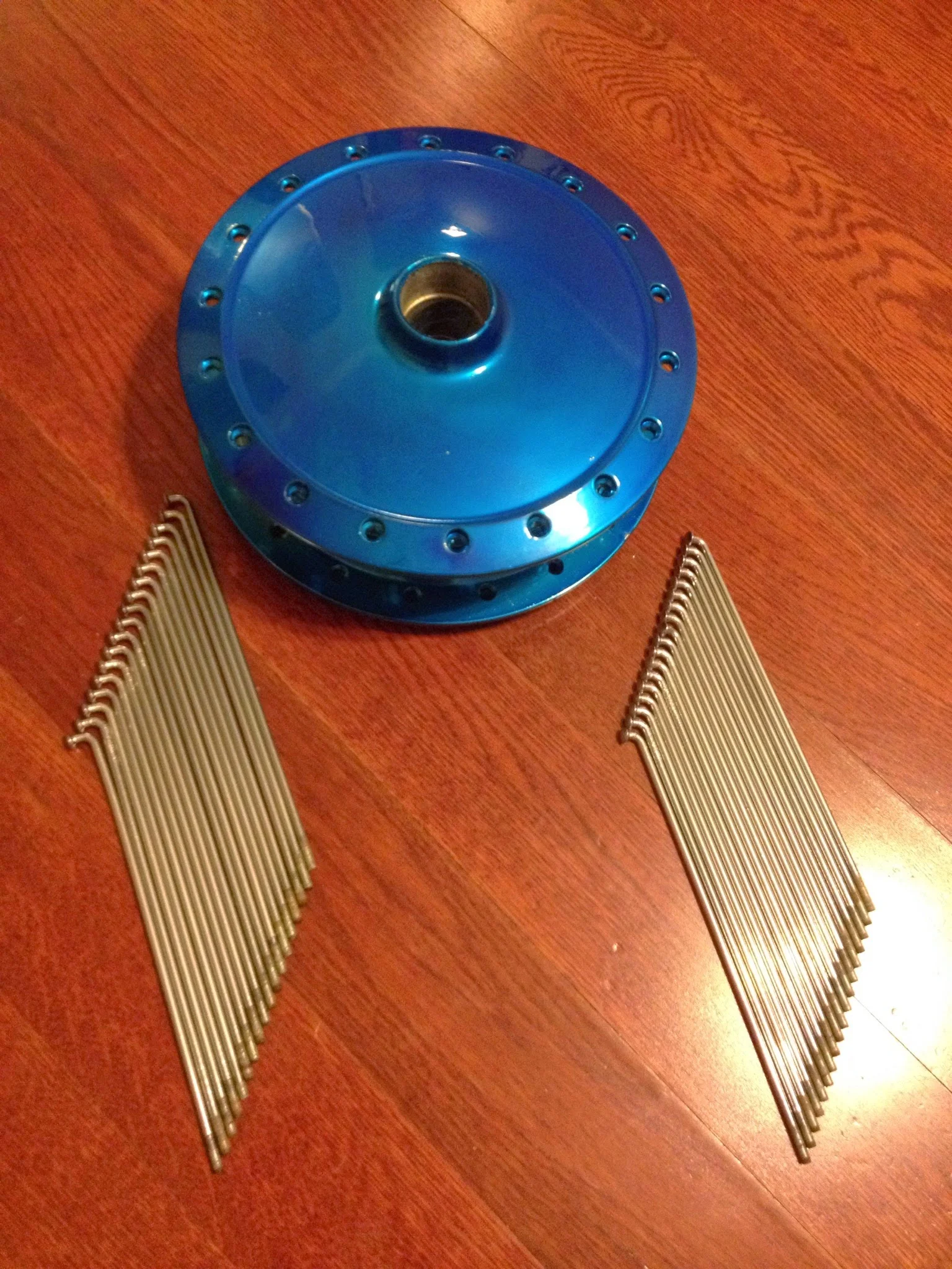
I got the wheel dissembled (my first wheel I’ve ever taken apart) and spent the next hour or so cleaning all the spokes, nipples, and hub.
Again, not hard…but time consuming. If I were rich and had a garage- I’d just sand blast it all (media blast, more like. Probably with walnut shells) but I don’t. So I use simple green and steel wool.
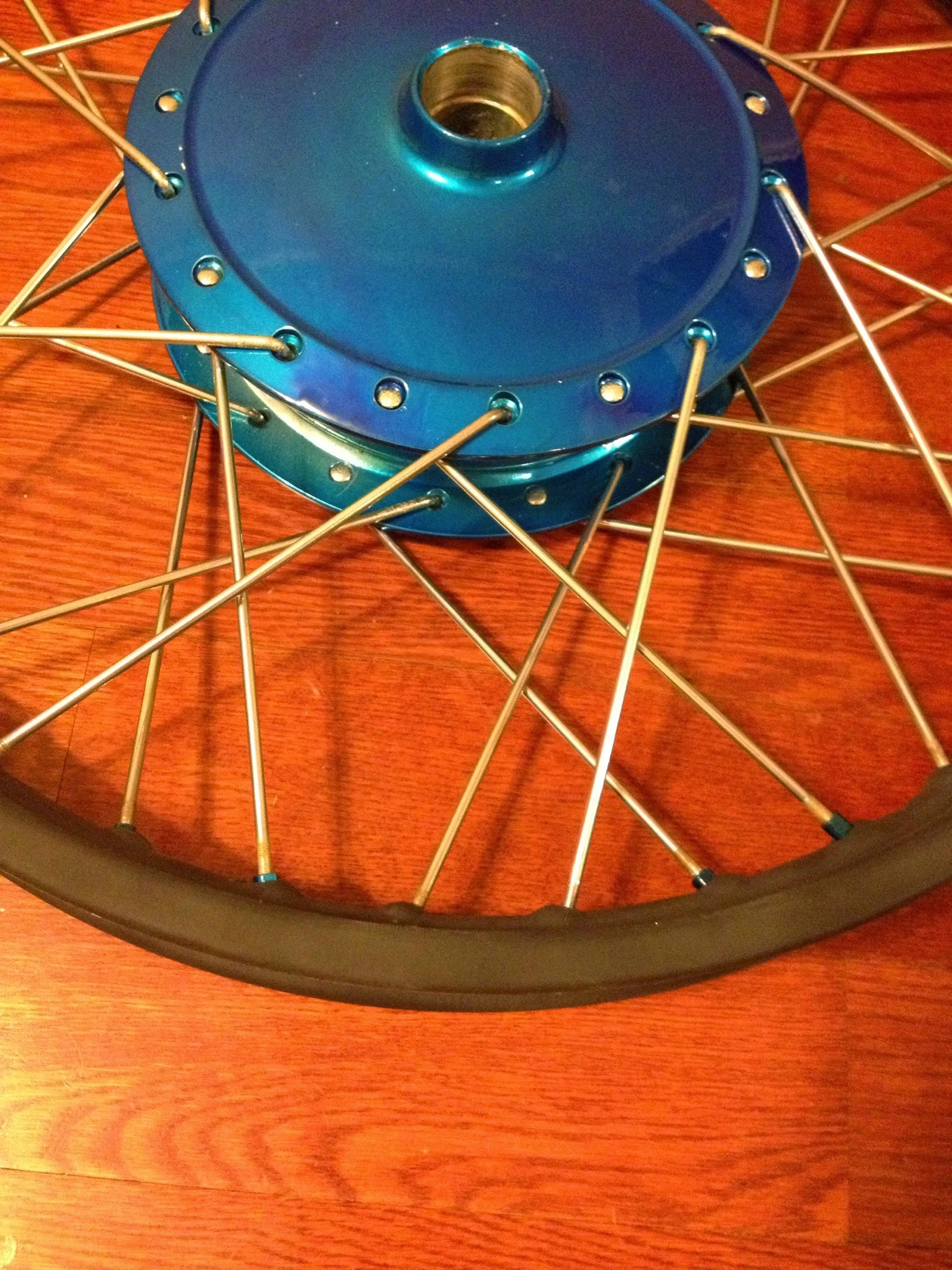
The old rusted spokes got sprayed with the “chrome” powder. Nipples got sprayed a candy blue (candy meaning it’s translucent, not a solid color when fully cured. It’ll show the layer of paint/powder below) and the hub got powdered chrome, then blue. Seeing as how I didn’t need to use the wheel for anything and it was a test, it went well.
Lacing a wheel is the hardest thing I’ve done. Harder than building an engine. I spent about 2 hours just lacing it. Now it needs to be trued. Since I won’t use it, doesn’t matter. But I might try and sell it.
I don’t think anyone will want to buy it, though…
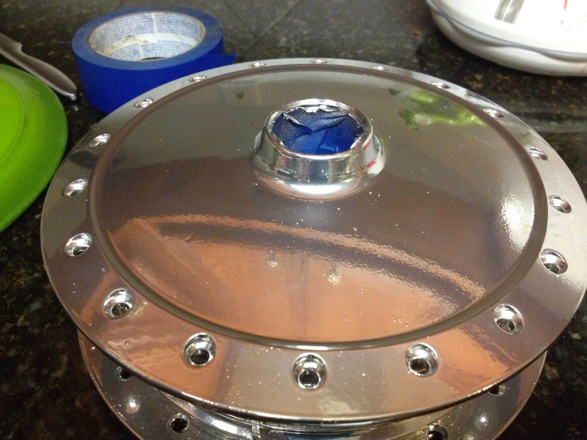
Chrome Powder. Color is awesome. Should have spent more prep time to prevent bubbles.
Rim was plasti-coated because it wouldn't fit in the oven.
The colors
Rainy day, and the light is about gone at 5pm when I get off work so I'm holding off on coating the cases.
I did do a couple of tests though. First one i did the two stage coating of a tin can. The chrome base and then blue color top coat. It came out looking like a hawaiian teal color.
Discouraged, i quit...and then curiosity got the best of me, so i grabbed the upper triple tree from the YZ250 forks and decided to give it a chance.
I'm in love.
Strippers and powder
When I got home I had a package from Eastwood sitting by the door.
Stripper and powder. In a more exciting world, that would have a different connotation.
I got the old ugly blue motor parts out and put the stripper on to the hard cured powder. And I let it sit.
The stripper worked really well, and I had serious doubts since I baked the original coat of powder on thick and long (over baked, in fact, hoping the color would change…wondering what I did horribly wrong to yield such different results from the color I was expecting. This over cooking led to the separation of the powder from the base of some of the letters. Fun fact.)
I had to run to the home improvement store to get some acetone, as water wouldn’t remove the stripper/powder/slime solution that resulted from 30 minutes of sitting on the aluminum parts.
While the purple gel sat on the parts and did its thing, I cleaned up the remaining parts in preparation of coating.
The engine cases had been “cleaned” long ago…and it took forever to do this. I tried many methods.
O.D.C. Old dirty case.
Of everything, cleaning with gasoline (which is what I did with the DT-2) was the easiest, fastest, and most effective. Things I tried that didn’t work as well-
Simple green
Pine sol
putting them in the dishwasher
putting them in the dishwasher again
Scrubbing manually with soap and water
Eventually what got them clean was a combination of all of the above over the course of a month or more. And “clean” is a relative term. Dirt and grime still clung to crevices. Yamaha uses a nuclear proof glue to bond the cases together in addition to the screws. Yama-bond, they call it. And it gets on things and doesn’t come off without slow, agonizing attention to detail
Engine cases themselves were scraped clean with a razor blade where needed, then scrubbed with a scotchbrite pad, then washed with simplegreen and #2 steel wool. Side cases were stripped with Dekote, rinsed in acetone, scrubbed with simplegreen and #2 steel wool.
I, like many other men (probably) am guilty of getting excited, getting in a hurry, and rushing things. This admittedly was the case with the first round of powder coating. I got the color in the mail, was super excited, and wanted to see what it’d look like. If I had the RIGHT color, it would have looked fine. But seeing has how I didn’t…
I’ve been afforded the chance to go through and better prep things. So the cases and covers have been stripped, smoothed, scrubbed, cleaned, and dried. They’re ready for powder.
But I think I’ll do a test to see how the color looks before going crazy. That’s the plan for tomorrow, maybe.
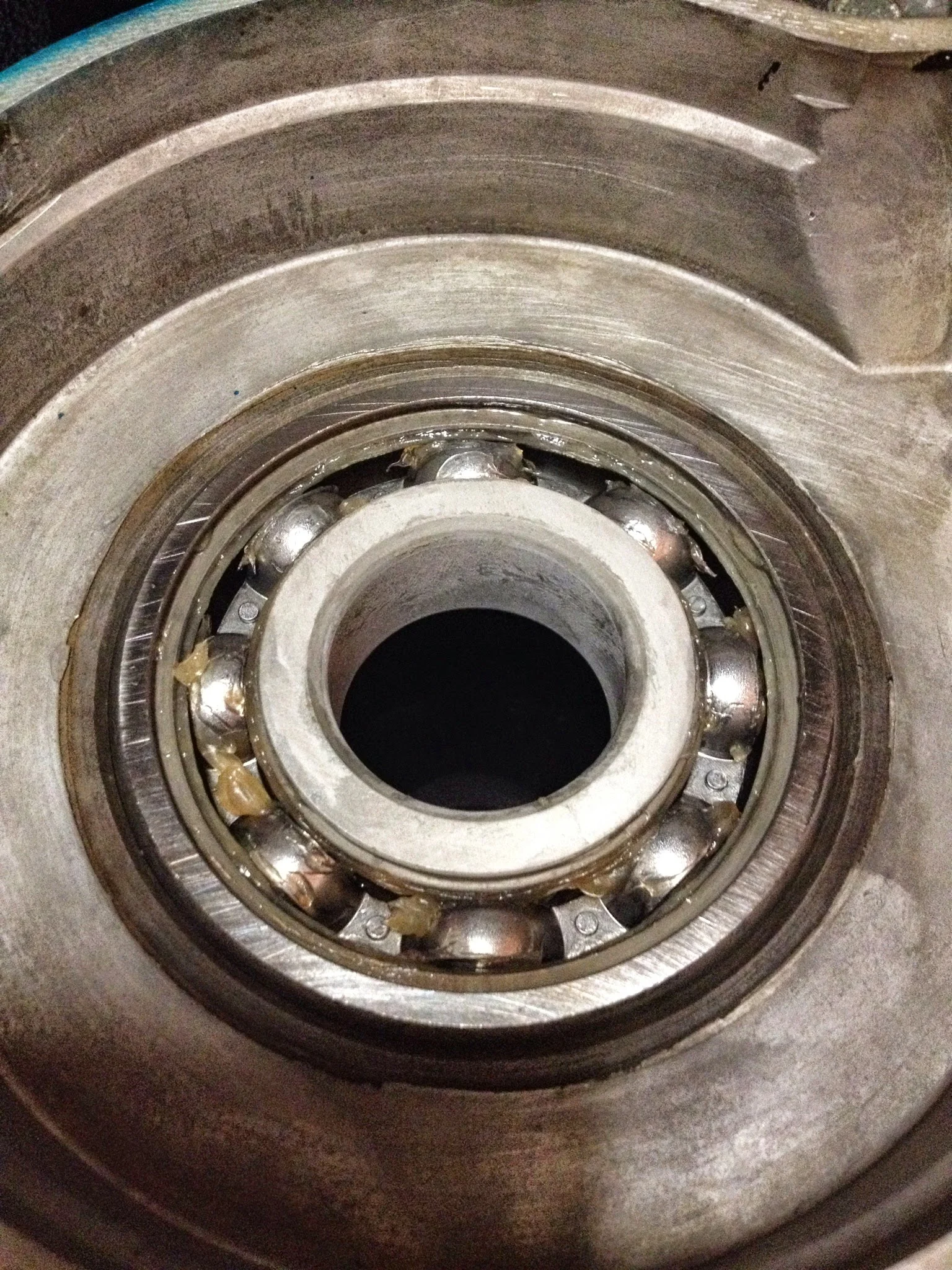
The nice thing about powder coating is that it affords a really easy, all in one step to put in new bearings.
The cases are machined to accept bearings with tight tolerances, obviously. Back in the Japanese factory these bearings would have been pressed in to place with a fancy hydraulic machine with tons of force.
Most popular way to do it today, and the way I’ve done it without fail countless times- Put the bearings in the freezer for a day or more. Heat the cases in the oven (have to do this to cure the powder anyway)
Cold bearings drop right in to hot cases. Thermodynamics in action.
Bearings are in the mail, so maybe I’ll wait until they are here and knock it all out efficiently. Either way, I’ll break out the powder gun tomorrow and do a test of the 2 stage color.
First stage is laying down a powder “chrome” which is just a glossy, highly reflective silver. Once that is sprayed, baked, and cured a translucent pearl blue will go over. The base reflectivity and the slightly transparent blue color should make a nice complicated deep looking (but not deep-blue colored) result.
If it ends up being dark blue..I’m throwing the whole thing out the window. The powder is from Eastwood this time (same place as my powder coating gun, same place as the stripper) and I have full faith in them.
Results later…
Suspension woes
The DT1 has been sitting in the closet collecting dust quite literally. It’s in my closet with my clothes…
I’d purchased some forks on ebay off a 94 YZ250. Awesome, inverted KYB creations with an insane amount of travel and awesome look.
For some stupid reason, Yamaha decided that the 94YZ was going to be a rarity as far as forks go.
Stupid YZ forks. So pretty, though...
The forks themselves are 43mm at the stanchion, not 45 or 46 like most newer versions.
The steering stem itself is most troublesome…28mm in diameter.
The old 1971 steering stem/lower part of the triple tree
Comparatively, the dimensions of the stock steering neck on the DT1 are this:
Upper bearing seat- 43mm.
Lower bearing seat- 49mm.
Not a big deal…this means that I need a tapered roller bearing for the top that is 28mm Inside Diameter by 43mm Outside diameter, 28 x 49 for the lower.
Except that doesn’t exist. Anywhere. Ever. It’s not a roller bearing, ball bearing, tapered or un, that was ever made or will ever be made for a price that I can afford.
So my struggle has been multi-fold.
Options-
Find different triple trees with a 25mm stem that will fit the awesome forks from the YZ250
Adapt the DT1 frame to accommodate the only 28mm ID tapered roller bearing made (28x52mm)
First option is out. Almost an model YZ 85 forks meet my 25mm stem requirement
(I spent a fair amount of time sourcing dimensions from allballracing.com and their fork swap app. It doesn’t directly tell me anything useful since my model isn’t supported, but it does tell me the bearing dimensions for all the other models it supports, and this, in turn, tells me steering stem diameter and overall neck diameter choices. All balls also has a list of all of its bearings, so I can see what my general options are)
I could use YZ85 trees, but I’d also have to get YZ85 forks since the bodies are a smaller diameter than the ones I have. Also…YZ80/85 forks are expensive because punk brat rich kids use this model of motorcycle to learn/train/race little wee-person motocross.
Option 2 is out because I don’t want to modify the frame at all. I want this all to be bolt on/off.
So I took a long shower last night. It was a cold night. I shut the light off in the bathroom. Closed the door, lit a candle, and brooded in the hot steam and water. I had to decide what I wanted to make this bike.
I’ve long wanted a TW200…a Yamaha fat tire monstrosity of a motorcycle. They’re hard to find for a reasonable price. But parts are not…And as it happens, TW200 forks meet my diameter requirements in that the stem is 25mm. The forks themselves are antiquated, traditional models with not a whole lot of travel. But in the end…I’m not building a motocross bike.
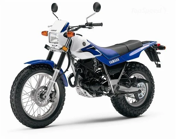
Stock TW200 photo.
I just really love those YZ250 shocks. I’m keeping them anyway because YZ forks are a direct and popular swap on the BMW F650GS’s and it turns out, I’ve got one of those.
So for $40 I got some TW200 triple trees on the way from ebay. For another $40 I’ve purchased the correct (in theory) tapered roller bearings. The TW and the DT used loose roller bearings back in their day, but cartridge tapered roller bearings are easy enough to find, theoretically better at handling loads, and I wanted to use them.
The choices at this point (there are always choices) are what forks to get? The TW200 supports 33mm forks, and there were not many 33mm fork options. The TW200 units will more than suffice, and no doubt they’ll be better than the old 1971 technology, though the 71 forks had 34mm stanchion tubes.
Further, the TW200 long used a front drum brake. Within the past 5-10 years, the newer models (this is a bike that’s seen almost no change since the 80s) feature a disc brake. The only change that was made was on the casting of the left fork.
So theoretically, I can find a newer style left fork that will allow me to put a hydraulic disc front brake set up on, any old right fork, a TW200 front wheel with a disc brake hub, and I’ll be in good shape.
Decision B- what to do with the rear? I can adapt a TW200 rear swing arm (maybe, researching dimensions on this) and put a monstrous tire on there.
Problems- TW200 uses a mono shock, the DT frame is set up for dual shocks.
The bike may look cool with an 18x3 tire up front and an 18x3 tire in the rear, though. We’ll see…
On the engine front, decided to get back to work because I’m tired of parts sitting on top of my fridge and under my sink. Bearings are on order as is powder for coating the cases.
Going a different route on color…
The color of garbage.
Originally they were going to be a crinkle blue (think valve covers of the 5.4l supercharged engine in the Ford GT) I went so far as to order the color and begin coating...and then I realized i was sent the wrong color. And I lost all heart, and have not touched anything since then.
Now they’re going to be a two stage candy with flat black accents. The frame is matte black. Triple trees will be candy blue. Body work, if I ever get there, will be carbon fiber.